


As I mentioned in my most recent Project Rough update (which I’d suggest you check out before you get into this one if you haven’t done so already), I’ve spent the best part of the last year playing around with with my ER34 Nissan Skyline’s suspension geometry. I’ve been doing this to not only try and maximize the available grip at hand, but to truly learn how each change affects the car’s handling and overall driving characteristics. Today, it’s wheel alignment time.
Since this was my first time attempting such a thing myself, I only focused on the basics – caster, camber and toe.

A quick online search reveals countless forum posts, tech articles and YouTube videos on wheel alignments, and the more of them I read and watched, the more my interest was piqued. The problem lies in the cost of testing every single combination that comes to mind – multiple visits to the local alignment shop would quickly become expensive. The only way you can really experiment is to perform the alignment changes yourself.

The desire to do just that led me down the dark and painful rabbit hole that is a four-wheel wheel alignment. Fortunately, GKTech graciously helped feed my silly curiosity.


GKTech has been in the Nissan aftermarket performance parts game since 2003 and is well known throughout the world for their innovative solutions at affordable pricing. Though they have branched out to support the growing Z33/Z34 market, the passion and love for Nissan’s R-chassis is still just as strong as it’s ever been. Without GKTech’s support, Project Rough would still be a hot mess.
Instead of going through and trying to explain exactly what I’ve been up to over the past 12 months, I will break everything down into steps that I feel are important for a DIY wheel alignment and, perhaps more importantly, what not to do. If I can save just one person the pain I suffered during my own experience, then I’ll consider that a win.
Warning: this is a big one, so you might want to grab yourself a coffee…
CHAPTER TWO
Take Notes
The first thing you need to do before even thinking about making an alignment alteration is to grab a notebook or some other kind of way to record your data. The last thing you want to do is blindly make changes and not know what worked or what didn’t and where you started. This is a game of millimeters (sorry, no imperial metrics here!) and just a turn or two can drastically change your car’s handling characteristics. Ask me how I know…

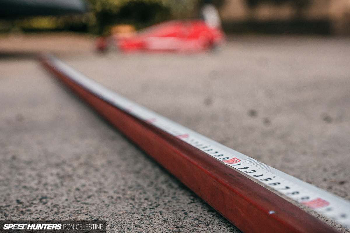
Speaking of millimeters, make sure you have a good tape measure or ruler at hand. At the end of the day, your measurement will only be as good as the device you’re measuring with, so don’t skimp out on this.
CHAPTER THREE
Zero Everything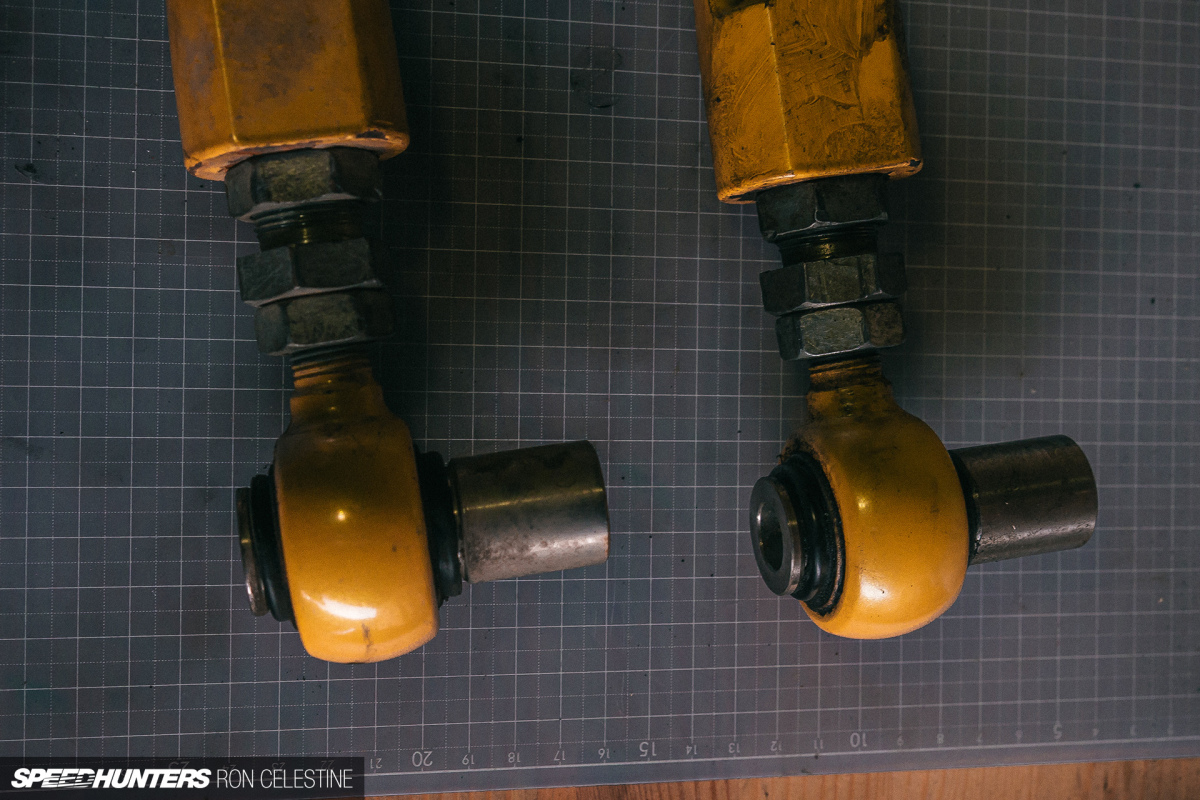
This one seems a bit odd, but if you’re attempting to do an alignment on your own, it’s best to start with a clean plate by zeroing everything out. This will also help you troubleshoot any problems that may arise, as if your adjusted measurements are the same left to right, then the results should also be the same.

It took me till I was basically at the end of my alignment journey to do this, and it led me to discover that Project Rough had likely been in an accident in the past (surprise, surprise) and wasn’t properly fixed. Thus, no matter what I did to adjust my camber, the two sides of the car would never match, even if I set the camber arms the same.
CHAPTER FOUR
Check Your Preload
Now’s also a good time to take a look at your coilovers and sway bar end links if you have adjustable ones. With regards to your coilovers, make sure the preload is set to whatever the manufacturer recommends. For Project Rough, the coilovers were designed by my friend Frank at Tuner Concept and he recommended 10mm of preload.

Unsurprisingly, my preload values were all over the place. This quick fix actually had a profound effect, so it shouldn’t be overlooked.

While you’re zeroing everything, put some anti-seize on your coilovers, a step that’s often missed in the excitement of fitting them for the first time.


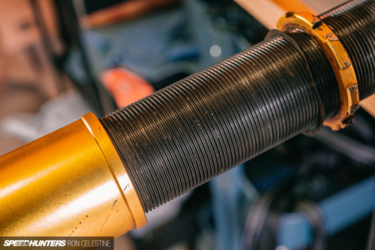
All four of my coilovers were seized, and it took some rust-penetrating spray, a heat gun and a large cheater bar to finally break them all loose.
CHAPTER FIVE
Build A Platform
When doing a DIY alignment, most people will use their concrete driveway or garage floor. That’s fine, but even if it appears to be level it more than likely won’t be, especially if it’s outside.

If you’re still planning on taking the car to an alignment shop afterwards and just need to do something basic to get you there, then you probably don’t need bother with this next step. If, however, you’re trying to obtain the best possible results, then you’re going to want to get your car perfectly level by sitting it on some sort of platform.
Ideally, this should be something you can drive onto without jacking the car up. If you have to jack the car, you’ll need to ensure that the suspension has fully settled once you lower it down again, and that’s another variable that can throw your results off.

I started off using wood as I had plenty of it left over from various projects around the house, but I quickly decided it wasn’t a great option as it can warp and crack.


I instead turned to carpet tiles to act as shims as they are relatively cheap (some places may even give you free ones, though I didn’t have that kind of luck) and don’t compress much. A bonus that comes with cheap carpet tiles is that they tend to be made of harder plastics and therefore are more rigid.

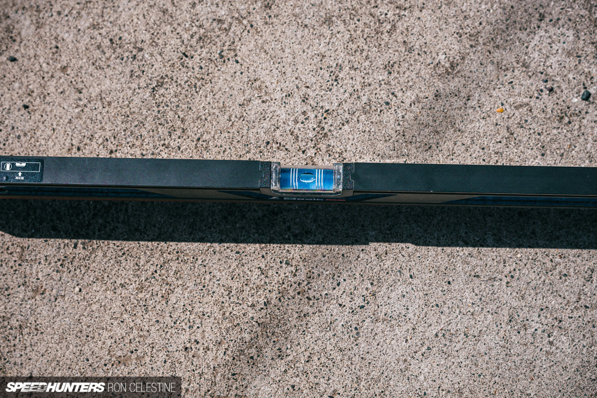
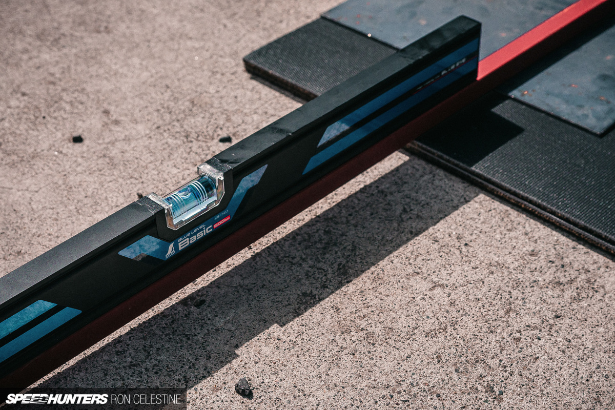

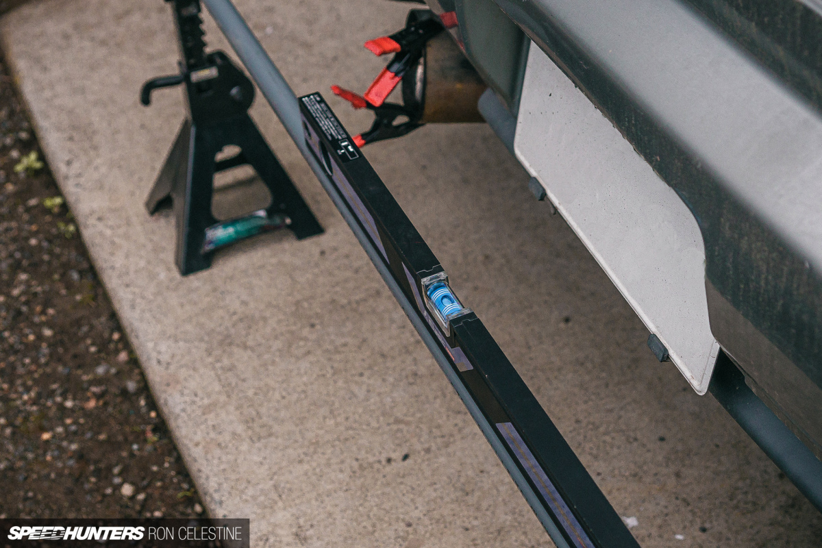
I placed a steel plate on each carpet tile tower to try and distribute the weight evenly, and give myself a perfectly flat surface to take measurements from. With a long extrusion bar and bubble level, I went back and forth adding more tiles until the level read zero.

Even though the driveway looked flat, just look at how many carpet tile shims it took to level everything up!
CHAPTER SIX
Set Ride Height
Now that you have a level platform to work with, you can go about taking measurements and setting your desired ride height. Adjusting ride height will have a domino effect on everything you do, so you’re going to want that set in stone first before making any adjustments.
You should disconnect your sway bars and place ballast that matches your body weight if you’re going for the absolute best results. Having said that, I didn’t have 80kg of stuff laying around that would fit in the driver’s seat, and I couldn’t find a set of cheap weights locally, so I skipped adding ballast but I did disconnect the adjustable sway bar end links. Note your measurements down and move on to adjusting the caster.
CHAPTER SEVEN
Caster
Nowadays, many cars don’t come with adjustable caster/tension rods – the R34 included – so to make proper changes here you’ll need to get your hands on a set of adjustable caster arms.

Along with the coilovers, Tuner Concept also has caster arms available for the R34 platform, so that’s what I’m using. But what is caster, you ask? Without diving too deep into it, the caster angle can control high speed stability, front end cornering effectiveness and steering effort.
When you adjust the caster arms, you’re changing the angle in which the tire rotates. Another way to look at it is you are moving the lower pivot point either in front of the upper pivot point (positive caster) or behind the upper pivot point (negative caster).

From my forum research, I noted that many Skyline owners run less-than-stock numbers for caster. I’m not sure why this is, but my guess is it has something to do with the HICAS delete. What I noticed when I lowered the caster angle was that turn-in felt quicker as the steering effort was less, however, mid-corner it felt like the front wanted to wander a bit and little inputs were needed. The steering also didn’t want to return to center, meaning on corner exit I had to manually return the steering wheel to the center position, thus not allowing me to be as smooth as I’d like. These are all things to be expected with less caster angle.

The art of measuring caster seems to be one of those things that still causes debate. To measure caster, you’re going to need to make a turn plate – an accurate way to turn the wheels 20 degrees outward and 20 degrees inward – and have a tool that can measure angles handy. For the turn plate, I sandwiched trash bags on the steel plates with a little lubrication in between them. I also made my own versions of the tools required to measure angles, though I’ll go over that a little later.
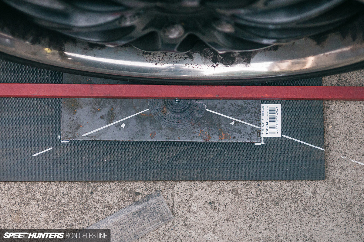
The trouble came when I tried to get the 20 degrees outward and inward. I first tried using a protractor and tape to mark out the angles on the ground, but I really didn’t feel good about that method. I then used trigonometry to help plot out exactly where the tires should be to get the desired 20 degrees, but unless I had that dead on in the middle of the plate, the results would be off.
Though not correct, I attempted to get as close as possible to 20 degrees with the previous tape and protractor method, and counted the number of rotations on the steering wheel. I zeroed-out my angle-finding tool, mimicked that number in the opposite direction and took my measurements. For now, I measured the distance extended on the arms and added as much caster as space allowed (I made sure the driver side measured a little less to help counteract crowning in the road).
Though not cheap, it might be best to try and get your hands on some proper turn plates or purchase a camber/caster gauge that has the 20-degree angles cut into them at the bottom. If you have your string box setup, you can use that combination but, again, those aren’t exactly inexpensive either. If anyone has any good DIY tricks, let me know in the comments. Until then, I’ll continue scouring Yahoo! Auctions Japan for a decent used set.
CHAPTER EIGHT
Camber
Next up is adjusting the camber. It’s important that you go in this order as changing camber will affect your toe. Unlike caster, measuring camber is pretty straight forward.
What is camber though? Again, without getting too deep into it, camber is the inward or outward tilt of the tires if viewed from the front or back of the vehicle. With negative camber the top of the tire tilts inwards towards the vehicle; with positive camber the top of the tire tilts away from the vehicle.

It did take me a few versions to get something that measured consistently. My first version was to take an extruded L-shaped piece of steel, cut it to a workable size, and make two holes that I could fit long bolts in. The bottom hole was taped whereas the top hole was created so I could slide the bolt up and down to match any size wheel.

I then stuck a digital angle finder to take my measurements, and a bubble level to make sure I was putting the tool on the wheel as straight as possible. Although I took a lot of care to ensure the bolts were the same length, the slop in the slot meant that the length of the bolt was always changing.
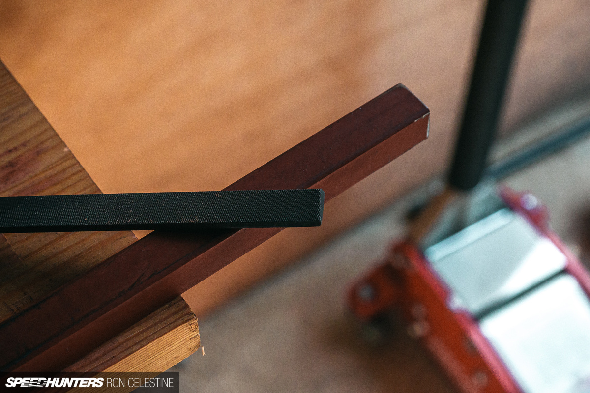
Version two of the angle finder did away with the adjustability, removing many possible points for error. I used an extruded square tube that I then cut to my wheel size.

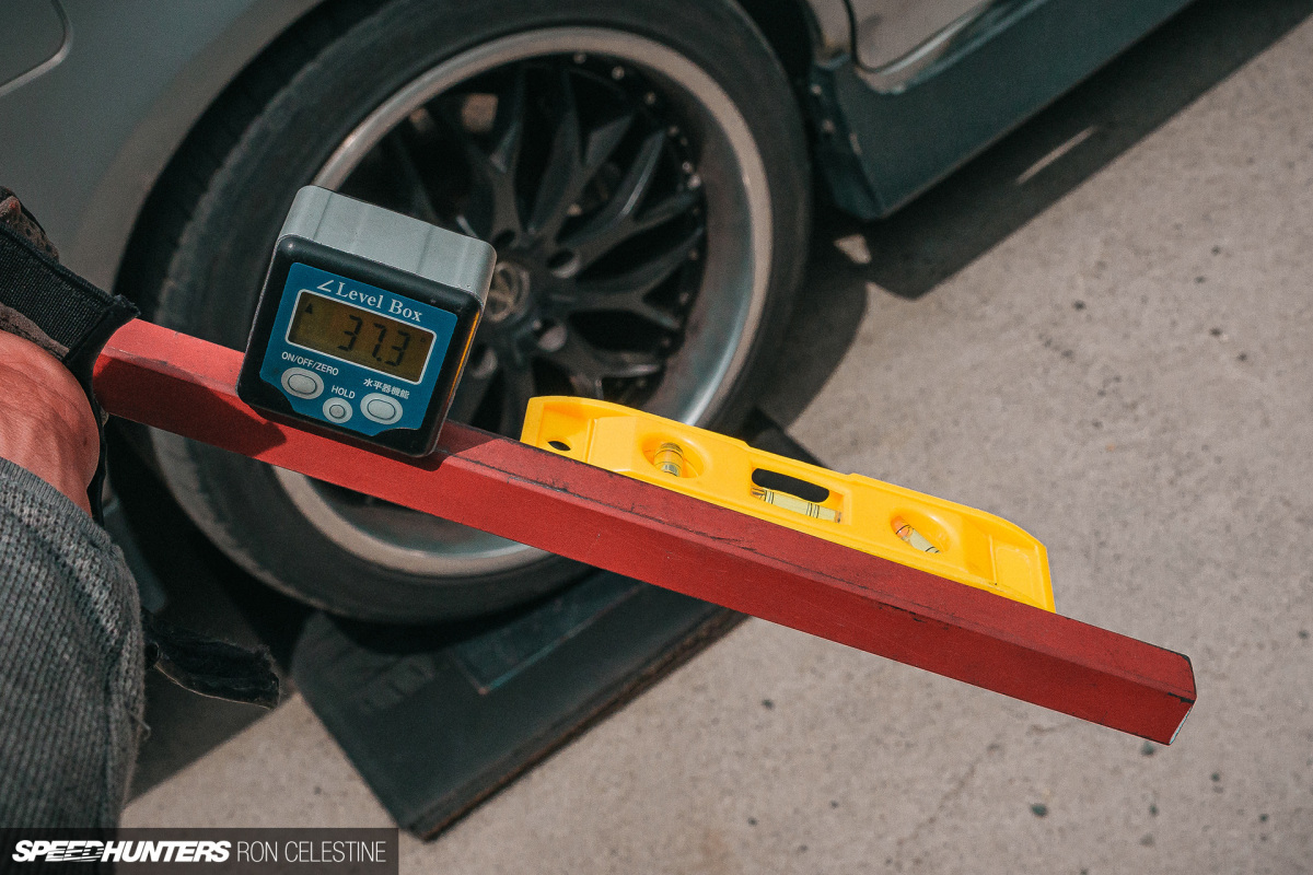

Once my digital angle finder and bubble level was attached I got measuring. This version had its issues too, as the digital angle finder had to constantly be zeroed-out when moving from each platform, and for whatever reason, it kept reporting a shallow angle for the front right wheel even though it visually looked closer to 3 or 4 degrees.

The solution was to do away with the digital angle finder, and replace it with my smartphone and an angle finder app that uses the gyroscope sensors. This version not only confirmed my visual suspicions, but was able to produce repeatable data.
Now that I had a device that was simple, easy to use and reliable, it was time to dial in the camber. Again, many vehicles don’t come standard with a way to adjust camber and Project Rough is no exception. Once again, Frank at Tuner Concept came to the rescue with some rear upper control arms, but I had to look elsewhere for the fronts.

You may remember that I had picked up a set of Cusco upper control arms from the GT-R specialist shop Veruza a few years back. These did have adjustability, albeit a very limited amount due to the way you adjust them. This meant that no matter what I did, it just wouldn’t be possible to get the camber to match up front thanks to the car’s previous accident damage that I mentioned earlier.

The fact that one of the bushings also looked like it was trying to escape from its home meant it was time for a change.
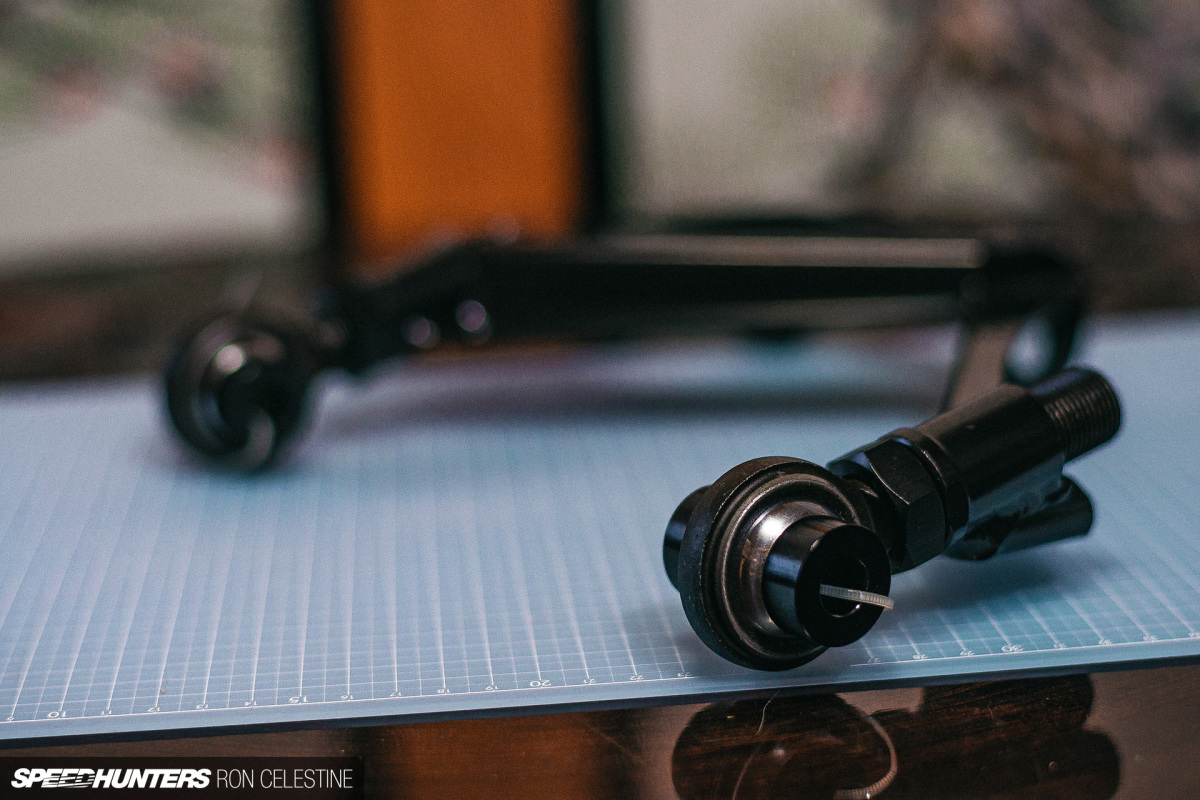


GKTech’s Front Upper Control Arms (FUCAS for short) were the perfect solution as the arms allow anywhere from 0 through to +30mm of adjustability. I love how solid and well-manufactured these are, and the Teflon-lined spherical bearings provide a more direct and predictable feeling.
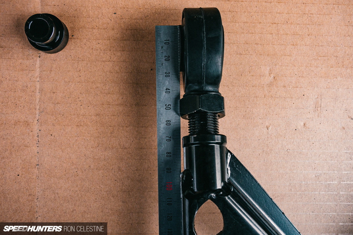

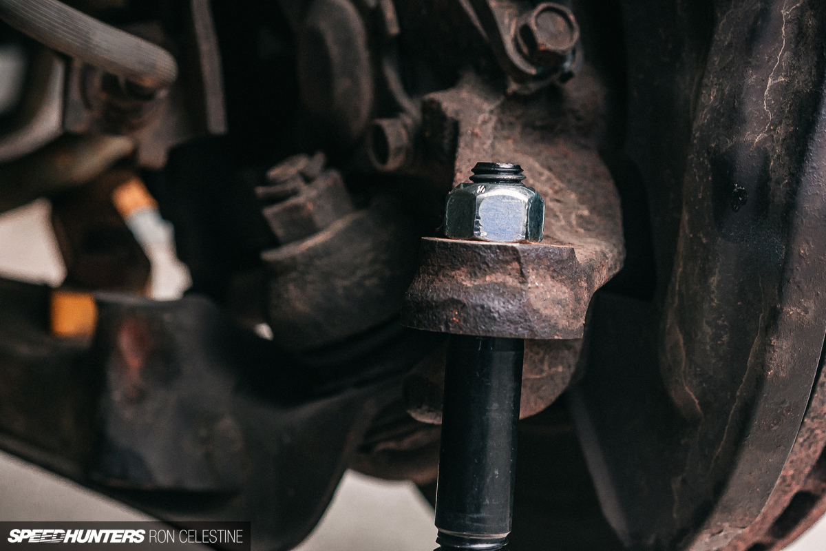
Installing them is pretty straight forward. You remove the coilovers to get access to the inner camber arm bolts, and then remove the outer camber arm bolt and out the arms come. To help ensure both sides of the control arms were adjusted to the same length, I used a cutting mat along with my ruler.

To put them back in, I found that replacing the outer camber arm bolt first made everything much easier. I could then use a jack to get a bit of extra help to lift the J arm up, and wiggle the inner camber bolts into place.
The only downside to the FUCAS is the fact that you can’t adjust them on the car, thus you have to jack the car, so I had to drive Project Rough back and forth off and on the platform to make sure the suspension had settled before checking my measurements. Again, thanks to the Skyline’s previous accident, I had to do this process many times as I needed to play around with the adjustment to find the balance. If you’re not dealing with a damaged car, you could just set both passenger and driver sides the same and be done with it.
Once again, keep track of all your measurements including the distances each length is set to.
FINAL CHAPTER
Toe
Toe is the one setting that you can change on all cars, and it relates to the angle the tires point when looking from above. If the tires point outwards, that’s toe-out. If they point inwards, that’s toe-in. Again, with a watered-down definition, a toe-in setting will reduce the tendency for oversteer as the tires are pointed inwards and will resist change in directions as a result. This will also improve stability at speeds. A toe-out setting will reduce understeer as the tires are pointed outwards and are already ready to change directions. Excessive toe-out can cause a twitchy and unstable feeling. I looked to forums to get a rough idea on where to start, and then played around until it felt right.
When going about measuring toe there are two ways that you can do that – the toe plate method and the string method. Though the toe plate method is the easier and quicker of the two, it only allows you to measure the toe between two wheels at a time (front or rear), which means the measurements to the true center of the vehicle relative to each other are unknown. This can lead to the angle being off, which is not good. So, string it is.
If you’re unfamiliar with the string method, you’re essentially creating a box around the vehicle that runs perfectly parallel to the center of the wheels. To make it easier, you usually want to have a bar that runs in front and behind the car, which you attach the string to. You then go from side to side, front to rear, making sure that the measurement from the center of the wheel matches the other side. If the front measurements are the same and the rear measurements are the same, you know you have a perfect box, regardless of whether the track width is different from front to rear.


Version one of my string box used piping that my landlord had laying around (yes, I asked for permission to use it first). I measured the front wheel base, added a buffer to ensure I had enough space, and notched slits making sure that I put them in the exact same place on both bars.

I then used fishing wire and weighed them down to complete my box. Since fishing wire has an incredibly tiny diameter, it can give you a more accurate measurement than using regular string. Again, we are playing with millimeters so you want the most accuracy as possible.
But this is where my first version struggled. The piping, although solid, wasn’t exactly the same diameter, especially at one of the ends where it necked down for some reason. I had a feeling it wouldn’t work, so really shouldn’t have spent such a long time testing that theory.

Version two used two 2-meter lengths of PVC piping. If you go the same route, double check that they are in fact the same length; the hardware store claimed these were 2m, but one was nearly 4mm longer than the other. This could really stuff up your toe alignment and you’d never know why things weren’t adding up.
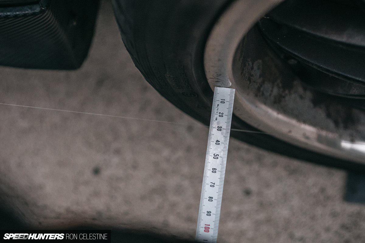
I cut the two PVC pipes so their lengths matched perfectly, notched them, and put them on jack stands both in front and at the rear of the car, ensuring they were level. I then strapped the steering wheel straight so it couldn’t move on me while I adjusted the tie rods, and strung my string box. I then went around the car, taking measurements from both sides of the wheel faces.
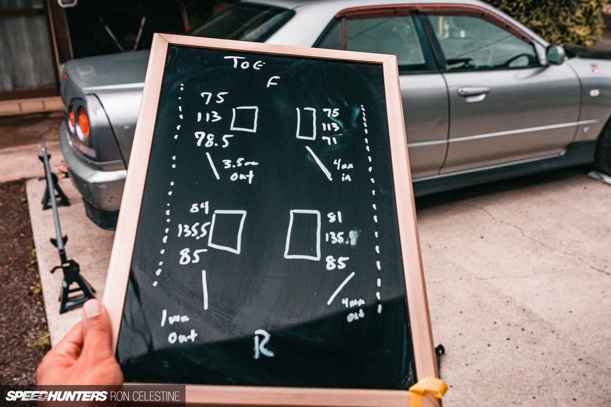
With reference to the string, the measurements could tell you how much toe-in or toe-out that specific wheel had. This is an example of the last measurements I did after the latest changes, and you can see how drunk my settings were. It handled as bad as you’d imagine it would too.
Depending on what kind of clearance you have, you might want to loosen the jam nuts on your tie rods to adjust them after you have your string box in place. The platform should help create a bit of extra space depending on how many shims you used. It then becomes a simple matter of making changes, checking the changes, and then locking the settings in once you’re happy with the measurements.

The rear tie rod jam nuts were fairly easy to break loose and make adjustments, however the fronts were virtually seized. I managed to break them loose, but when it came to tightening them up again, it was virtually impossible to keep the settings.

GKTech came to the rescue again with their M14 Super Adjustable Inner Tie Rods. Even though I’m not running rack spacers, different knuckles, or have adjustable lower control arms, these inner tie rods will suit all those upgrades.

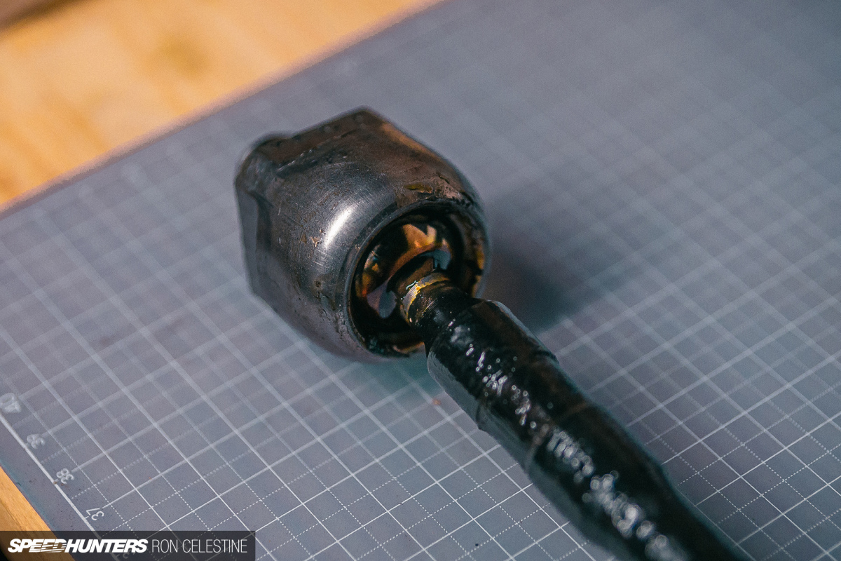
It was a good idea that I removed the inner tie rods too, as they had no resistance left in the ball joint and simply flopped around. It makes me wonder about the rear inner tie rods…

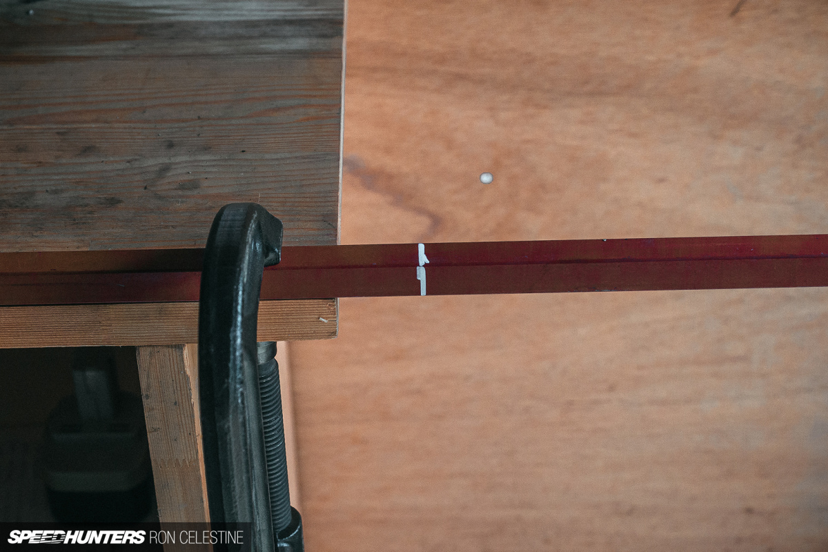
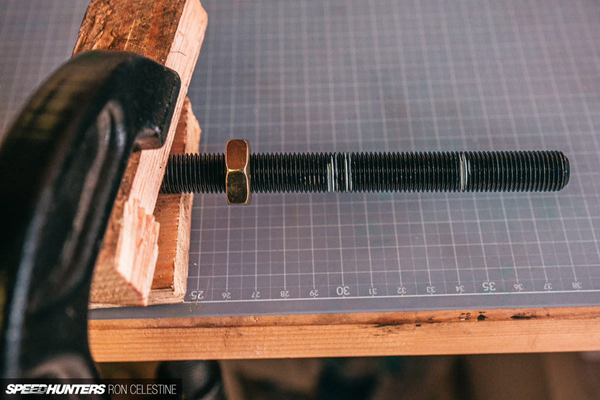
Since I wanted to reuse the boots for the inner tie rods (they were in good shape), I had to remove the jam nut from the old tie rod. To do so, I had to clamp it down and use a wrench and hammer combo on the nut. There’s absolutely no way you can remove this while it’s on the car.
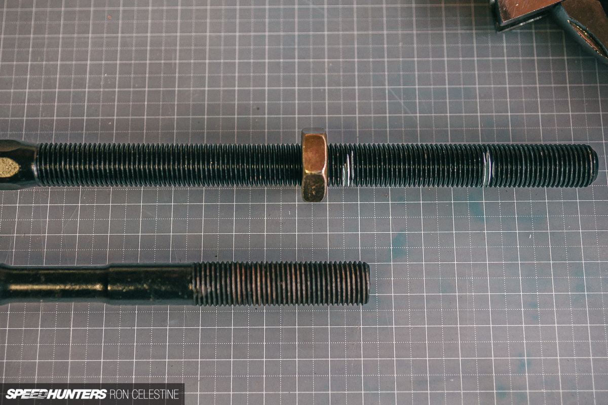

With the old inner tie rods out, I measured the length (many times) and cut the length. Depending on if you’re keeping the stock outer tie rods or not will play a role in how much you cut. For my application, I needed to cut more than anticipated as I was also changing the outer tie rods to GKTech’s High Misalignment Kit. Also, make sure you leave the nut on whenever cutting to length as it will clean up the threads.


I’ve heard nothing but amazing things about installing a proper bump steer kit, and GKTech’s High Misalignment kit checked all the boxes. With the ability to correct up to 25mm of bump steer, I was keen to play with the adjustment and see if I could notice a difference.

With the GKTech inner and outer tie rods in place, I set the shims to 15mm and gave it a test drive. I immediately returned home as I felt like the car wanted to kill me at the slightest hint of a bump. I changed the setting to 5mm and it felt pretty good – better than ever in fact – but I was curious to see what would happen if I split the difference and went with 10mm.

As it stands, 10mm seems to be the golden ticket for my car. It glides effortlessly over bumps and in some instances evens handles them better than my Honda Stepwgn. Seriously, why didn’t I install these earlier?! I’m curious about how much bump steer is actually there and want to build a bump steer gauge that I discovered online, but that will be for another time…

Project Rough drives straight, the steering wheel is straight, and overall it handles in a very predictable and responsive manner. That’s everything I was aiming to accomplish while learning the ins and outs of a DIY wheel alignment.

I can nitpick and say the rear doesn’t rotate as much as I’d like it to because the toe setting isn’t out enough, or that the camber setting is a bit too aggressive up front, but the great thing is I can now make adjustments whenever I see fit.
Just not now, because I’m tired of alignment stuff. I want to enjoy Project Rough for a while, and what better way than with some time at the track. Stay tuned for the third and final installment in this ‘Big Grind’ mini series…
Ron Celestine
Instagram: celestinephotography


Things are starting to get interesting now. Your new house is really a great place for all these DIY projects, eh Ron? Hahaha!
Haha I have a list THIS BIG of stuff I've always wanted to do. The house was definitely one of the means to do said list ^^
Couldn't be better timing for this, as I'm planning to tackle a DIY alignment on my 02 WRX this weekend! Very excellent summary of your journey.
Thank you! Hopefully I was able to save you some headache and help the diy process go smoothly! Let us know how it goes
Made turn plates from 3/4” plywood I had laying around and used a trash bag folded on itself between them. Worked beautifully!
Love these types of step-by-step write ups. Even better that you did it with budget solutions rather than spending a bunch of money on smart strings or similar (not to knock smart strings - they are awesome if you want to spend that money).
Thank you! I try to do everything as much DIY as possible ( do my detriment at times lol) sometimes you gotta spend a little cash but I want to show people that you don't need to simply throw money at things to get good results.
Nice. Very thorough. I understand why the alignment shops charge so much.
Thank you! Ya.. there is a lot of tedious work involved. Especially if you're playing around with caster and camber as well
Can you please clarify the caster measurement?
What does turning the wheels +/- 20 degrees do?
Around 10 years ago I bought a Nagisa Auto geometry adjustment kit. I think it cost around ¥40,000 at the time, but its certainly paid for itself by now. Sadly N.A. no longer sell it, but it's been a great tool for setting up cars after building them, etc.
Maybe they come up on Yahoo from time to time? Worth looking out for, as they'll be a lot less hassle than figuring out how to make one's own, and suffering the trials & errors of it all. Kudos to you Ron for getting it done against the odds.
If you're ever down Chiba way, drop in and say hello. You might like the hobby car & motorcycle workshop we built, and the projects that continue taking shape.
Hmmm I'll have to take a look on the auctions to try and find that. I found a few others that inspection centers / automotive schools use here and it was about that same ¥40,000 that you mentioned. I think if I was planning to do alignments on other people's car (or my own more often) I think I'd make the investment and buy one. Definitely have my eye on some turn plates tho as it would be nice to adjust caster a bit more accurately lol.
I'm a bit far from Chiba but def would love to stop by and check it out!
Thanks for sharing this Ron. I've just gone through this with my 1974 Fiat 124 Spider. I've only driven it about 1000 miles, but it had horrendous bump steer and was always wanting to wonder. Tires were also wearing horribly uneven up front. String alignment ended up revealing it was .75 inch (19mm) toe out, though camber was good. Suspect ended up being a tie rod that was severely bent and screwed all the way in. I ended up rebuilding the control arms with fresh bushings and balljoints and replacing both tie rods. I did a fresh string alignment to factory toe (.25 in toe in) and wish I had really looked into aligning it 1000 miles ago. Its amazing how much proper suspension geometry can change the handling of the car.
In my case, I am still taking it to the shop to get an alignment next week. Luckily, my front has factory adjustable caster, camber, and toe and I'm with you on how difficult it can be to accurately measure caster at home, plus installing shims for the caster/camber adjustments in the driveway.
Excellent work!
That was fun to read Ron as usual, I love the detail you put into your articles!
It's also been my experience that even at workshops with an alignment rig, it's no guarantee that the operator
will have any real knowledge about the fundamentals of suspension geometry. Most places are only going to
check toe and thrust alignment and call it a day.
Lol y tho haha.
Glad you're enjoying the updates!