
In our last segment, we showed you the initial build-out of the chassis. The chassis is the foundation for this project, much like a strong cornerstone sets the foundation of a great house. Now that the foundation has been poured, (or welded) the build and detail work begins from here. In this post we’ll take an in-depth look at the build process for some of the other major portions of the project such as the exhaust manifold, third member, and front end. We’ll also take a closer look at the small parts and details that must be considered when building an ultra lightweight car. It’s quite easy to look at a finished car and simply see a 1 piece drag front end, however rarely does one get an understanding of the process involved in creating such intricate one or two off products, until now.
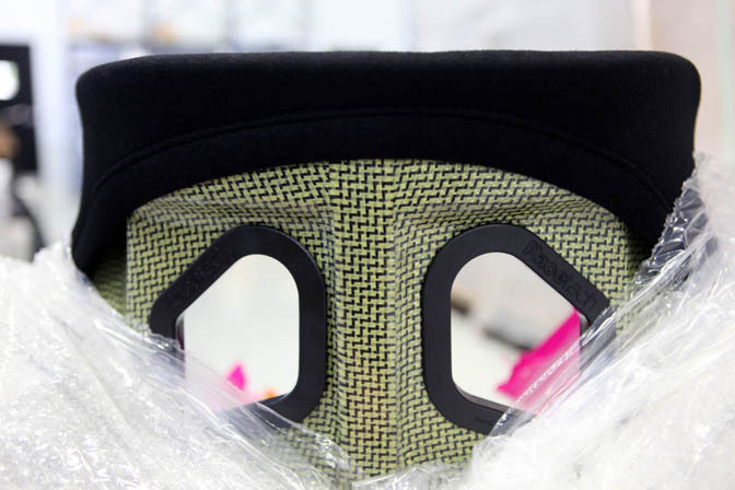
Not just any seat would do for this project. Wanting the best in safety and comfort, we opted for a Carbon/Kevlar RaceTech seat with integrated head restraint. If you’re not familiar with RaceTech, check out many of the leading GT and Touring cars around the world and you’ll likely find a racer sitting comfortable in this seat. This seat not only provides optimal protection, but it also reflects on the car’s roots, helping to give a street car feel over the typical carbon shell found in most chassis cars.
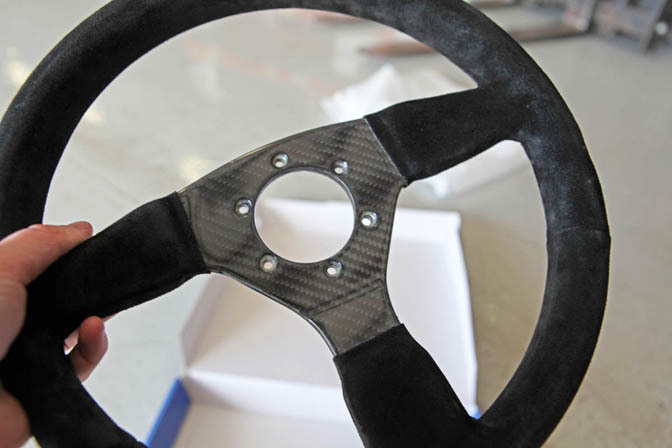
Continuing with the lightweight theme, we opted for a Sparco carbon fiber steering wheel. This wheel is made 100% of carbon fiber then wrapped in suede. While a steering wheel doesn’t seem like a place to save a ton of weight, ounces eventually equal pounds so getting rid of weight wherever we can is a priority, that and the full carbon goes great with all the other carbon that surrounds this car.
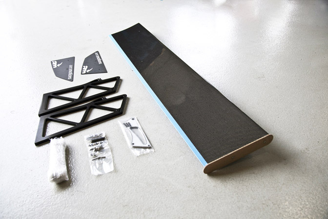
We opted for an Aeromotions wing on this car to help provide down force without disrupting the great body lines of the Supra. We’ve worked with the team at Aeromotions on Road Course wings in the past and they’re aerodynamic geniuses. So when it came time for a wing that would provide the down force we need without disrupting the aerodynamic profile too much, it was an easy choice.
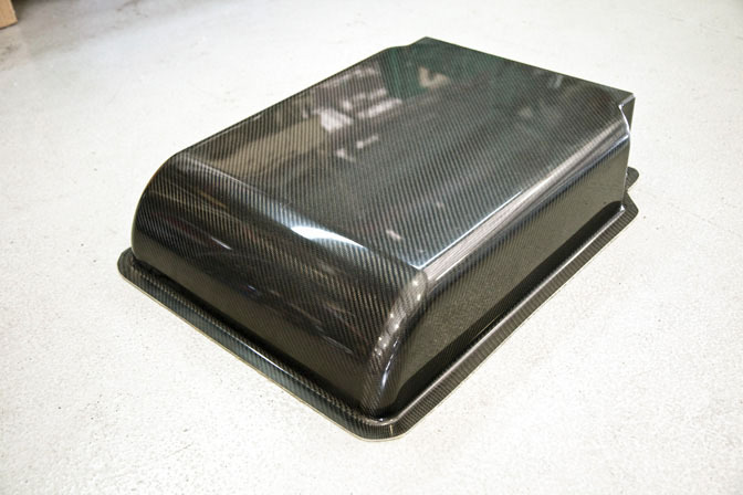
Beneath the engine sits a containment tray also made out of carbon fiber to help prevent liquids from getting on the track should an engine failure occur.
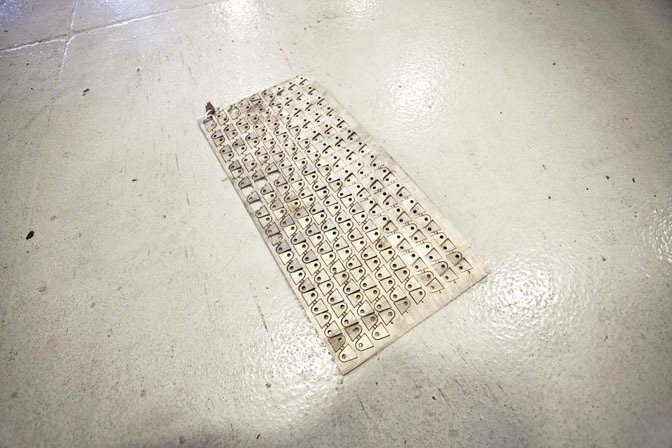
The window frames and other mounting hardware is fabricated out of titanium on this car, however Ti tabs aren’t something you’ll find on the shelf so we had these custom laser cut out of sheet titanium.
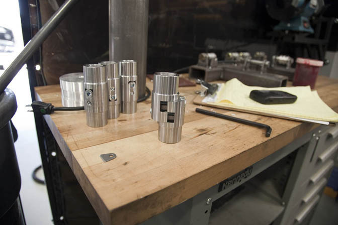
While the tabs were being cut we also had engine hook pickups produced as well. These mounts remain on the engine at all times and connect to custom hoist tubes we made. With just 60-90 minutes between rounds it’s important to make sure that an engine can be replaced as quickly as possible.
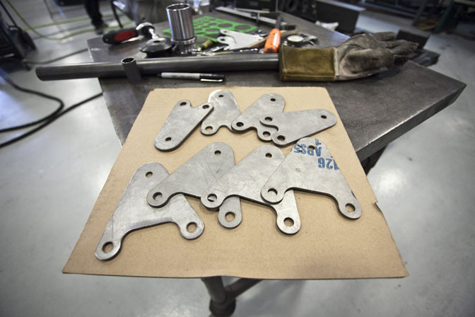
Many sanctioning bodies require portions of the front cross member to be removable. In an effort to keep the chassis as stiff as possible and still follow the rules we used these trick detachable clevises to allow portions of the front end to be removed as required.
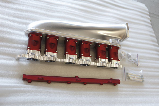
Hypertune makes some of the best intake manifolds on the market, and the 2JZ Race manifold they provided for this car is no exception. When you’re dealing with over 50lbs of boost and multiple injectors, achieving a proper fuel mixture is essential. This manifold comes with red runners from Hypertune, however these will be re-anodized black before getting bolted onto the race 2JZ.
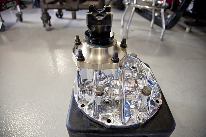
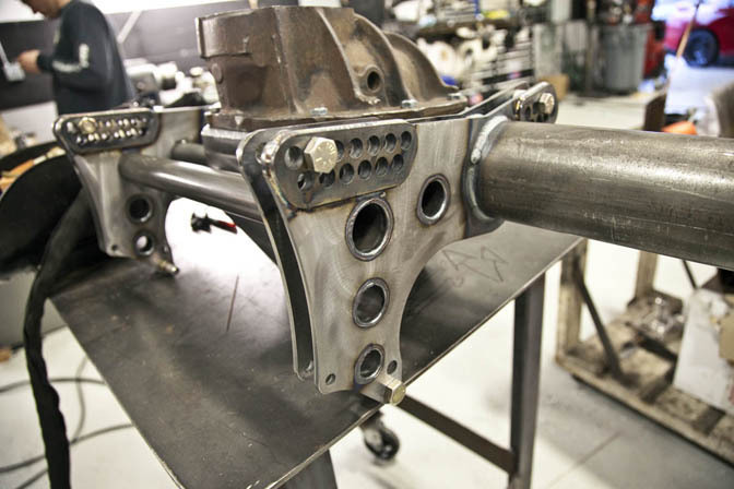
Another important part of a drag car is the rear end, also known as the third member. For this particular car we opted for a Strange 9 inch rear, fully polished, and a custom housing made from scratch here at the shop. The third member is a crucial portion of the chassis, as it’s what allows the 2,000+ hp to make its way to the ground. Through four link and other adjustments, the load, direction, and traction can be adjusted to ensure the car gets as much out of the tires as possible, while staying as straight as an arrow.
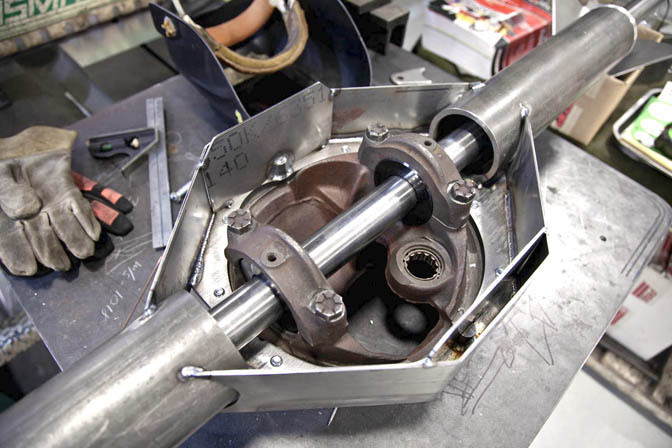
We start off by using a mockup rear and use an axle jig to make sure that the spacing is correct and axles stay true.
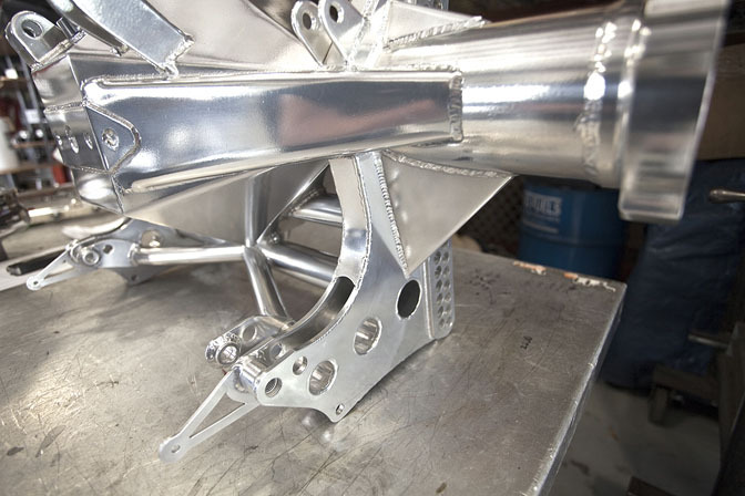
The outer housing then begins to take shape, each piece being carefully cut and bent into place to seal off the housing and hold the rear end fluid.
With the shell complete, the next step is adding on the brackets for the 4 link and other suspension points to mount to. Having as many adjustments as possible with the 4 link allows our crew chief to optimize the setup throughout testing.
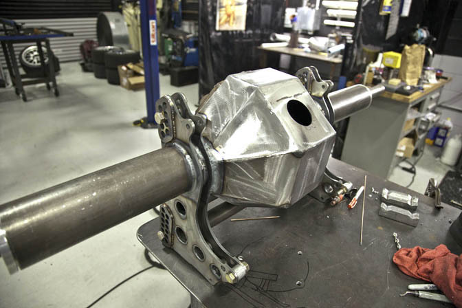
With the outer housing complete, the welds are ground smooth and the fill hole carefully drilled. A spout will then be welded on with a removable cap to allow the rear end to be serviced and fresh fluid installed when required.
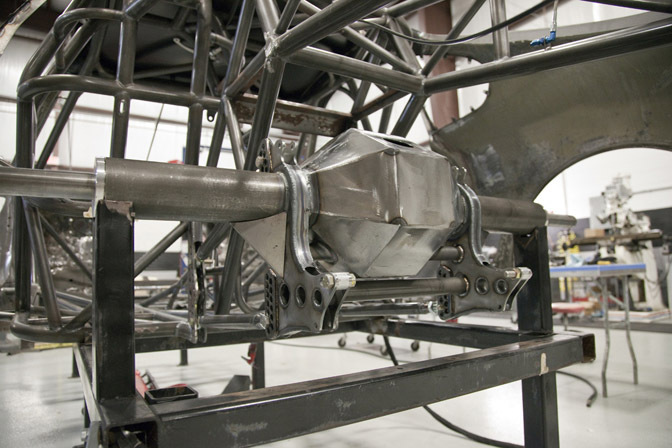
The housing is then placed into the chassis jig and squared up. From here all of our mounts and links will be built to help keep things square.
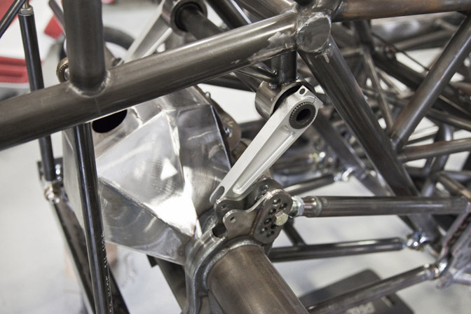
Above the 4 link is the mount for the anti-roll bar. The bar itself is integrated into the chassis and linked together to the rear housing allowing for precise adjustments.
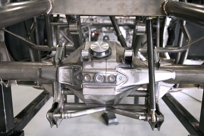
The finished rear end is mocked up in the chassis. You can see all the intricate mounts, axle shafts, and details that were fabricated from scratch in this view. A close look also reveals sanctions built into the bottom of the rear to allow it to be strapped down inside the trailer.
With the fabrication concluded, the finished metal housing gets cleaned and coated in a high temp silver paint. This helps protect the metal and keep surface temperatures at a minimum.
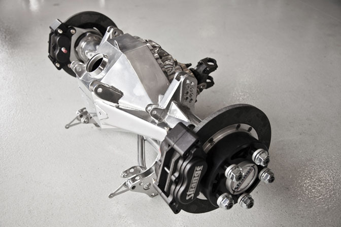
With the coating complete, the Strange axles and carbon fiber brakes get installed and the third member is ready for the cars final assembly.
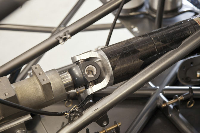
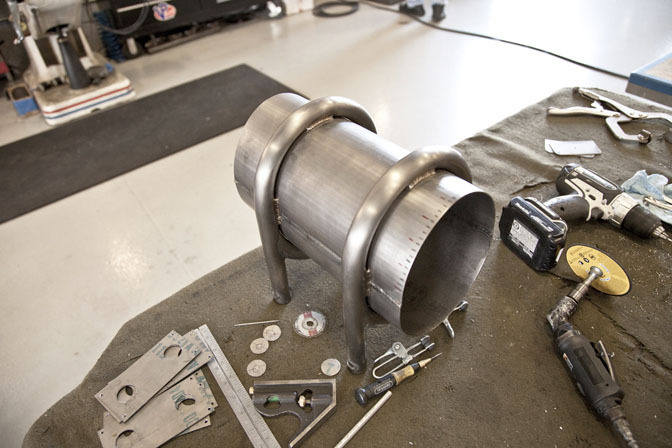
With the rear complete, we test fit it, and the transmission, and install our Carbon Fiber driveshaft. The rules require a complex driveshaft loop surround the universal joint portion of the shaft to contain these parts should a failure occur. Keeping in mind that this shaft can spin in excess of 10,000rpms and is less than a foot from the driver, it’s a welcome and important part of the safety requirements.
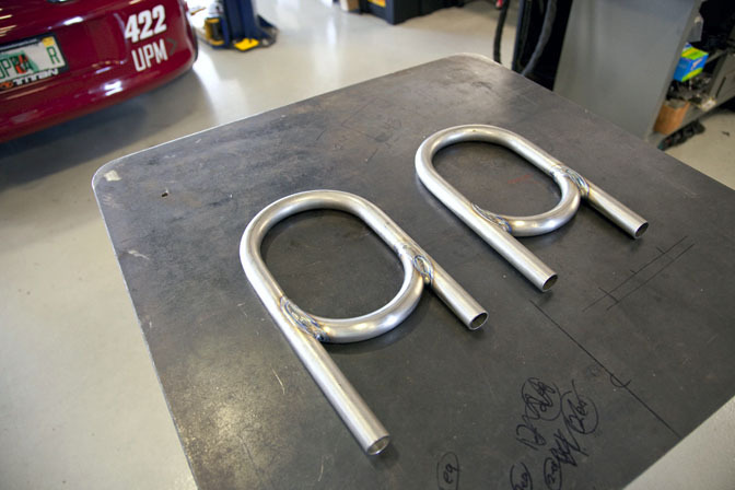
Naturally, a standard driveshaft loop made out of chromoly wouldn’t suffice for a project of this caliber, so we opted to make our own out of titanium. Here you can see the initial loops have been carefully bent and welded together.
These 2 loops are then carefully linked together by a single sheet of titanium that is carefully bent in small increments to form the oval shape before being welded in place. If you look closely you can see small tick marks, each of these marks indicates a shift in the metal in our press, where it is crease bent.
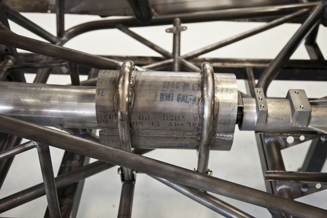
This is what the finished piece looks like in the chassis after being slipped into the chromoly receivers built into the chassis.
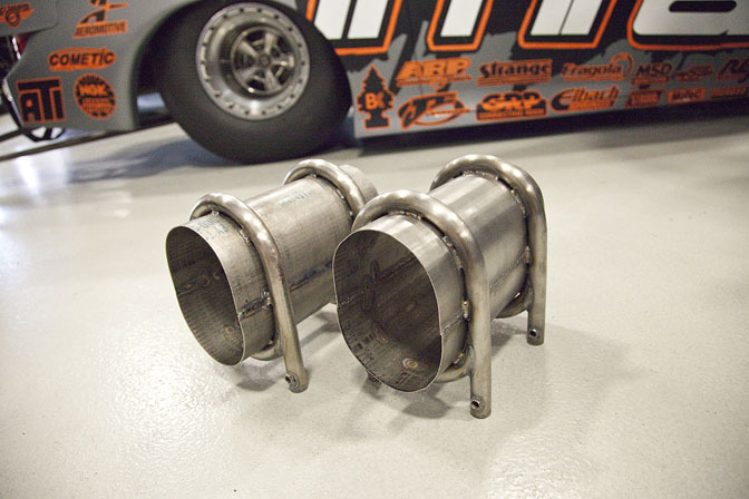
Since the car will be raced in Bahrain, some 7,500 miles away, we opted to fabricate a second spare loop out of titanium.
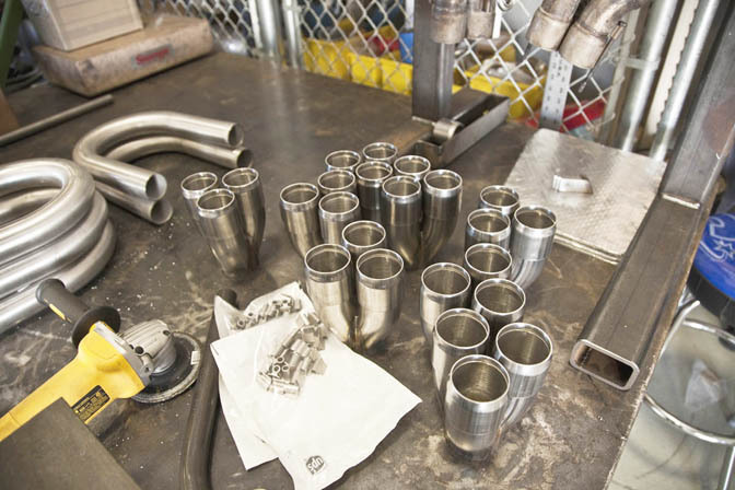
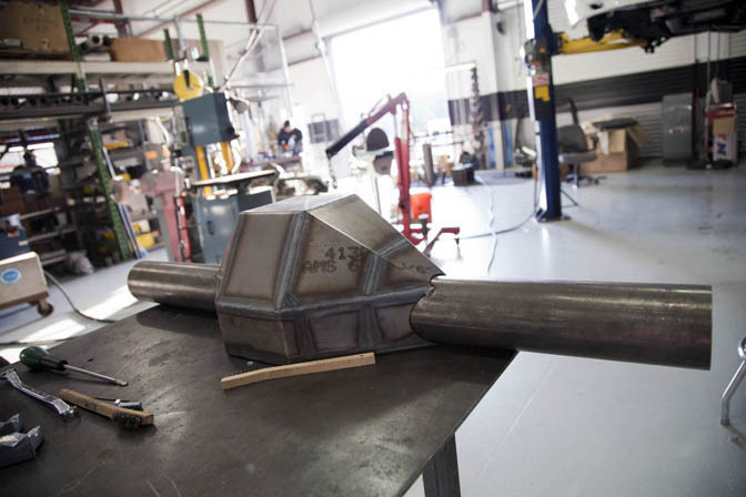
With the rear complete, it was time to move to the front of the car and fabricate the custom engine components, turbo piping, and the 1 piece front end. For the headers we start with raw tubing and collectors that are laser cut to our specifications for perfect fitment. When dealing with such a large framed turbocharger and the tight constraints of the factory frame rails, tight collectors and a precise bends are required.
The top portion of the header begins with a laser cut header flange made from 321 stainless, its mounted to a jig to ensure no warping occurs during welding. From there the top portions collectors are built, and then removed from the jig to be placed on our mock up engine inside the chassis.
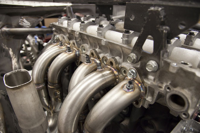
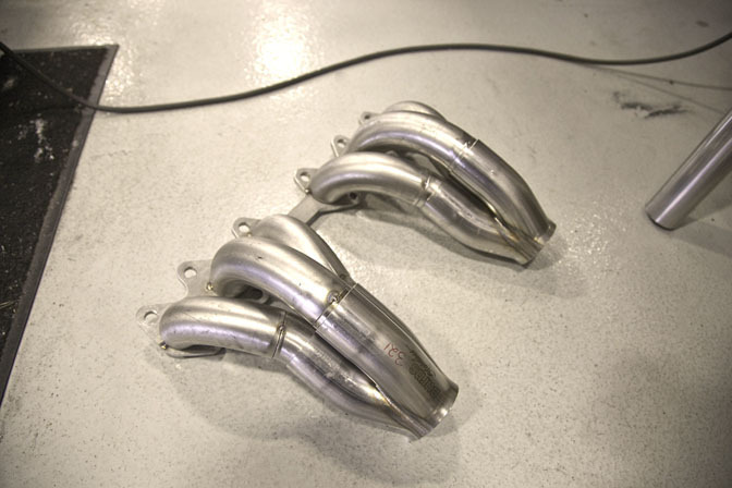
We mock the header up, create the long tubes from complete radius u-bends and circles, and then cap the top portion off with a V-Band. The V-band mount allows us to clock the turbo precisely to match up with the inlet that is to be custom molded into our front end later. In this picture you can also see the individual EGT sensor mounts that allow for precise monitors of each cylinders exhaust temperature for tuning.
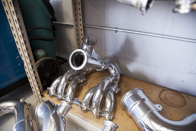
The header is then removed from the car and sent off for coating. Once it returns, it is placed on a labeled shelf until it’s ready to be placed on the engine. Three headers where made for this car, one for the car itself, the other 2 which will be bolted onto fully dressed spare engines placed on custom made engine carts.
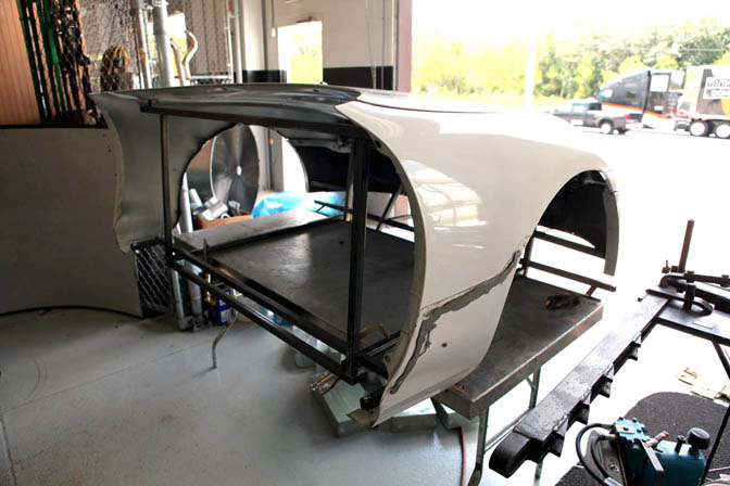
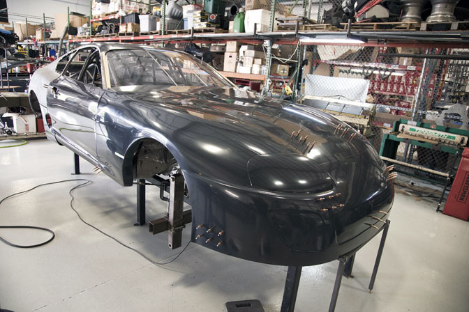
Next up is fabricating the custom 1 piece front end that will be molded from carbon fiber. To start the process we create a jig and assemble a stock Supra front end. This helps ensure the body lines stay square during transit and the body lines remain consistent as it would be from the factory.
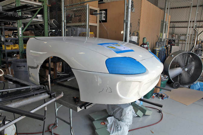
With the front end mocked up, it was time for our fiberglass fabricator Doug Gibson to get to work. Doug has years of experience building audio enclosures out of fiberglass, so he treated this as he would a big speaker box. He started off by stacking craft foam and bonding it to the bumper portion. We needed to improve the slope of the front bumper slightly for aerodynamics and this provided a great base.
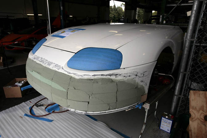
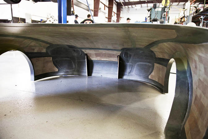
With the foam in place, layers of fiberglass and body filler are carefully layered onto the base and then sanded to form the shape required. While this is a 1 piece front end, we wanted to maintain many of the lines found on a stock Supra. Here you can see the intercooler and brake ducts being carefully formed into the bumper.
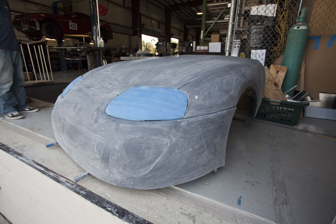
Once we were happy with the shape, the entire front end was shot with multiple coats of primer and finish sanded down to 800 grit, before being sent off to have a giant mold created, and a carbon fiber replica formed in one lightweight piece.
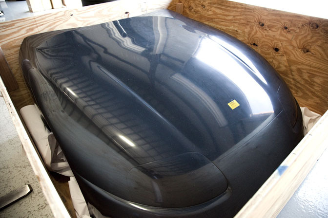
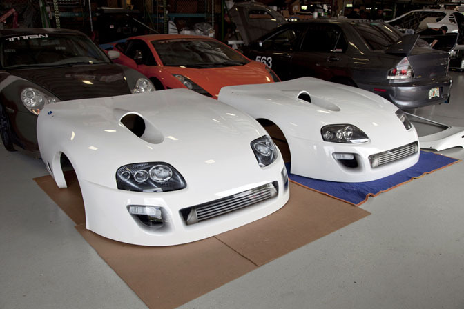
A few weeks later and the finished gel coated carbon fiber front end arrives in a giant wood create to protect it. For this project we had 2 front ends made, one designed for the track with a smooth surface and air brushed effects, and a second front end that would be used while the car was on display that incorporated functional Supra headlights.
Honeycomb material similar to that found in the airline industry is used on the inside to help maintain the shape while keeping it lightweight.
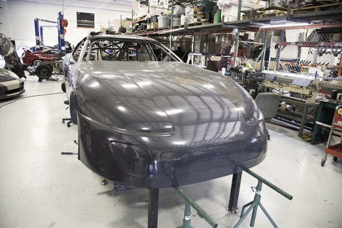
From here we test fit the front end on the chassis and begin working on the mounting structure.
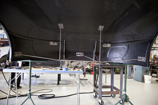
More lightweight titanium tubing and laser cut plates are used to help make the cage that will mount the front end to the chassis. After each run this front end is removed to service the car, and it must travel in excess of 200mph on track, so having a solid mounting frame is very important. Once the frame is complete is permanently bonded to the carbon structure.
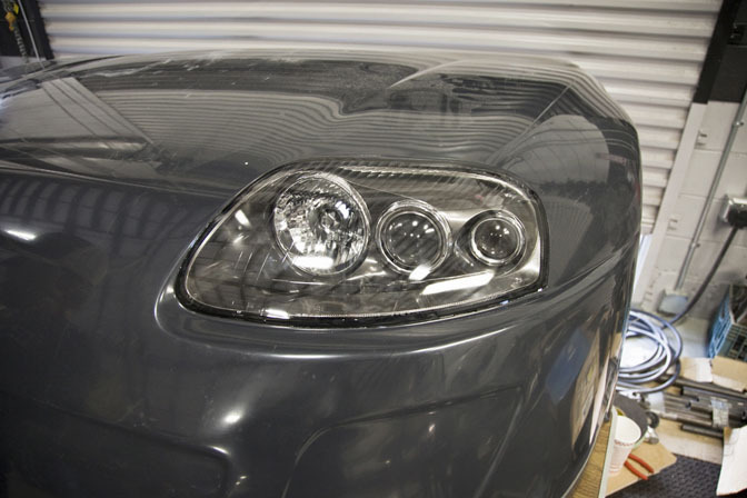
The cage is repeated on the second front end, only this front gets the light portion cut out and functional 97-98 style factory headlights are molded in.
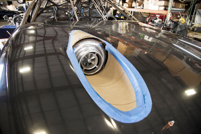
Starting with large cardboard tubes typically used for shipping paper, we begin mocking up what will soon be the integrated turbo scoop.
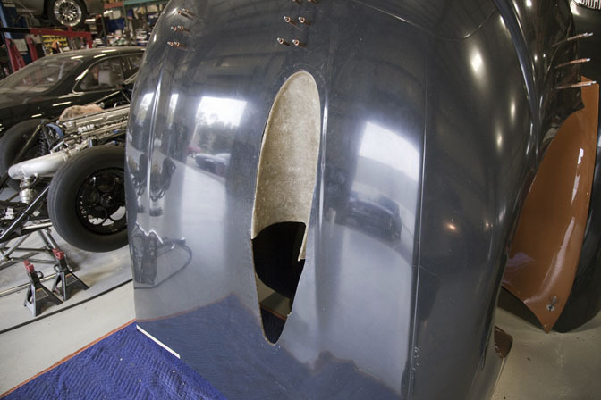
The scoop is then transferred into fiberglass before being finish molded into the front end.
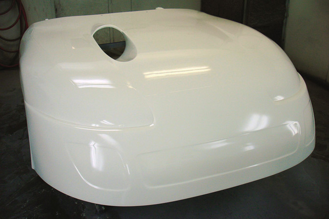
A few coats of primer later and it’s off to our painter where it’s shot in a fresh coat of the Super White base being used for the rest of the car.
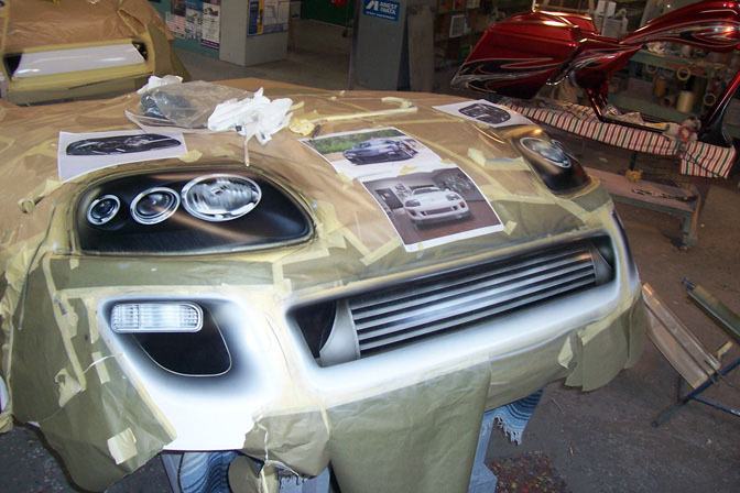
With the white base freshly dry the front ends are transported to airbrush wizard Chris Cruz. Chris was faced with the daunting task of making the headlights, intercooler and inlet ducts look as if they were 3 dimensional, hiding the fact the entire front end was 1 solid piece. The end result is nothing short of amazing, with even the smallest details such as the welds in the intercooler making their way into the finished piece of moving artwork. Chris repeated this process on the 2nd front end painting everything but the lights, just as they were on the race version.
A few coats of clear later and the front ends where back in the shop resting comfortably as they await the chassis to receive it’s finish work, and final assembly to begin, which you’ll see in installment 3 of this buildup blog.
-Titan Motorsports
OFFICIAL SPEEDHUNTERS SUPPLIERS


skills to pay the bills
Very sweet looking car , as always you guys are on top of the game !!!!!!!!!!!!
TITAN #1!
Awsome build!
I see it's already running
http://www.youtube.com/user/titanmotorsports#p/a/u/0/s7GyQomsiEw
THose are the front ends for the drift cars next year eh???????
There's another video showing him lifting off the gas after maybe 3 seconds of acceleration and still running a 9.3 second pass rofl.
Outstanding build! If I was spending all that money I probably opted for a custom billet rear end from Chrisman Driveline Components. Anyhow, nice job guys!!!
awesome!!
What's the point of airbrushing the intercooler and lights?
The level of craftsmanship here absolutely blows me away, great job guys!
spend copious amounts of money on something thatll take less than 10 passes down a drag strip in a part of the world where no one except the extremely rich will appreciate it...
hm, sounds like a real sound investment to me. im glad money talks so loudly.
this is going to be the hardest f$#@%^g supra in the world when it's done
whaaaaaaa... spendid work!
the terminator called he wants his rear end back. JEEZUS
One word........ DAAAAAYYYYYYYMMMMMMM!!!!!!!!
That supra is gonna be a force to be reckond with.
This is one of the better builds I've EVER seen online. Its incredible what happens when resources are properly invested! Great job Titan! Its absolutely amazing!
Paint work on those front end's looks absolutely amazing! It seriously took me awhile to tell the real headlights from the painted ones in that last pic. I love the detail going into this build, keep it up!
These are some of the best blogs I have ever seen. I would like to know the theory behind the exhaust manifold being 3-2-1? Is there some sort of advantage here?
I've never liked airbrushed front ends, but that guy's good.
Won't be able to tell the difference if I didn't know.
un-fucking-believable
Miss informed comments again... Drag racing is huge in the Middle East and a broad mix of grass roots to wealthy guys take part.
Car is also already complete.. http://bit.ly/nhIoFK
This is the reason why I chose to study engineering!
Indeed very nice, pure godlike! BUT the driveshaft loops that you made out of titanium, if I zoom in I can see that you haven't welded it properly, or is my eye doing me a trick? It looks like you have both blue areas and grey areas. Blue areas is because you have let oxigen into the weld to quick, and grey aswell. The grey areas is very very hard and can crack at any time. If it is grey, and you drop it to the floor, it will go into 100 pieces, like a cristal glas.
I hope Im wrong for your sake.
Sorry about the bad english.
// titanium certificate welder from Sweden
Appreciate the Kind words guys, it's great to have a customer with such a great vision, the trust in our shop to delivery his dreams, and the resources to make such a project possible. Ebrahim has been a dream to deal with and we talk at least once a day about the project, he's very involved in the build and knows exactly what he wants.
As far as the headlights are concerned, Kanoo is a diehard Toyota fan and wanted to retain the factory look of the Supra, only on steroids. Stickers wouldn't do a car like this justice so we found an artist talented enough to get the results we where looking for and keep the front end looking as if it where still multi-piece.
As far as the header design, with the factory frame rails we are extremely limited with space, the 3-1 collectors on each side allow us to run the proper diameter tubes, a large frame turbo, and still keep it within the frame rails, something that would be very difficult to do. We've tested other setups in the past and found this to work the best for our application given these constraints.
This car will likely be used and raced as much if not more than any import here in the states. The UAE takes import drag racing very seriously and holds 8-10 events during their season. It's many back to back weekends of racing, and it will be great to see this car put to use. Kanoo also has a Toyota/Lexus dealership in Bahrain so it's important we stay true to the brand.
Fabrication work is top notch, amazing how much work went into this. Congrats to all involved, especially the guys @ Titan. Proving once again you guys are THE BEST in the business
Fabrication work is top notch, amazing how much work went into this. Congrats to all involved, especially the guys @ Titan. Proving once again you guys are THE BEST in the business
Superb quality! Amazing detail going into this project!!
Titan great work and your skills are impressive!!
Why wasn't CFD or other testing involved to get the final flow through that giant turbo snail... I know its a lot of work but other teams do it and in a car of this caliber ever bit counts.
Regardless you guys really do have the right connections to build some of the most badass drag cars around.
amazing job ...