
Mike Bradley is no stranger to drag racing, and he has been a keen fan of the triple diamond brand from the start. Cutting his teeth in his 4WD EVO 2 ‘LTZPLA’ he got the drag racing bug bad, but despite a powerful engine package Mike never really had much success in the EVO2. Mike was smart enough to see the light and quickly realized that 4WD drag racing was never going to get him the sort of times he wanted.
Sticking with the Mitsubishi brand, Mike enlisted the help of Kerry from Auckland’s Top Gear Autotech to build a custom chrome moly tube frame chassis to fit under a late model EVO 8 shell. The Pro Stock style chassis converted the EVO 8 into a RWD configuration and turned the engine north-south. The new chassis also locates the driver on the left side of the car which helps with weight transfer off the start line.
One of the biggest problems with drag racing a factory 4WD EVO is drivetrain strength and STM have broken more drivetrain components than most! Converting the car to RWD allowed most of the drivetrain weaknesses to be overcome by fitting purpose-built drag components that are up to the task of handling 1400-1500 hp and the huge stresses that come from launching with two huge sticky slicks.
The car will be powered by an STM methanol drag engine and a Garrett GT45 turbocharger to produce around 1 megawatt of power!! (1000 kw). The power will be transferred to the ground through an air-shifted clutchless liberty gearbox and slider clutch. The diff assembly is a hand fabricated 9” housing with a Strange alloy centre which will provide a reliable and bulletproof driveline.
While nobody is expecting the car to set records off the trailer, the team is aiming for mid to low 7 second time slips at around 190 mph. Stay tuned as STM will bring you the build of this car as it progresses.
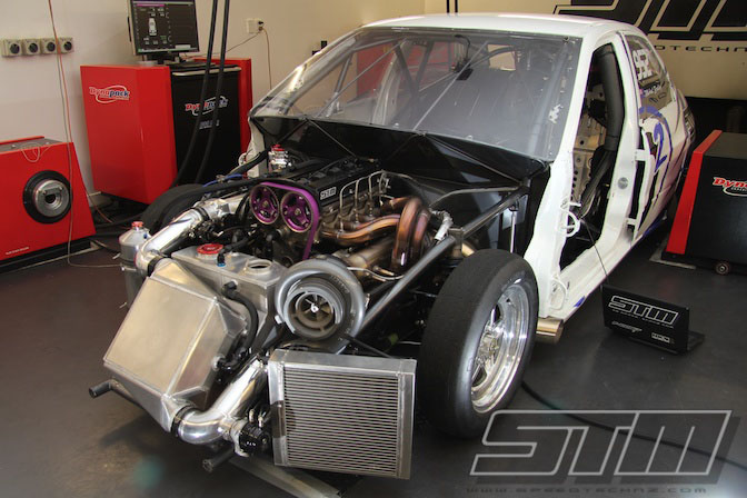
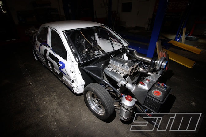
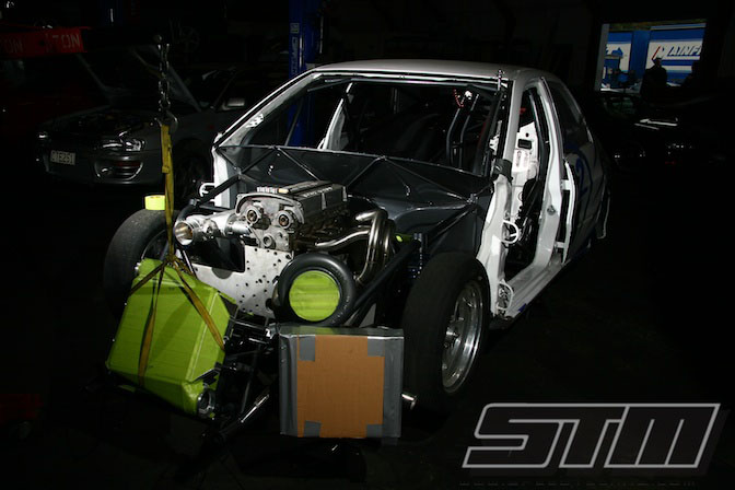
Mike’s car was delivered to STM as a rolling shell. While it looked pretty complete, there was a lot of work ahead of us, and a tight time frame if the car was to make its debut at the 4 & Rotor Nationals at the end of January 2011!
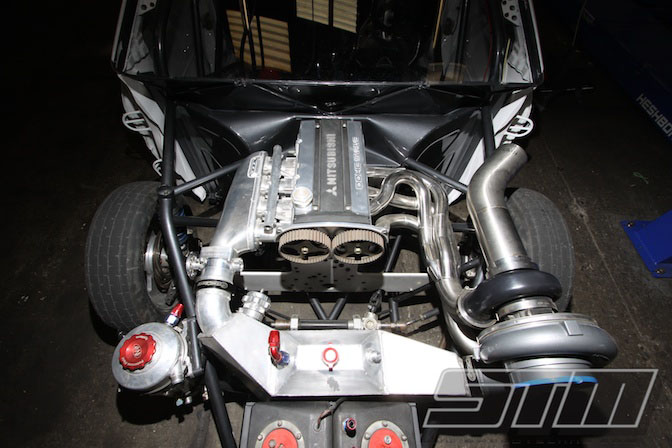
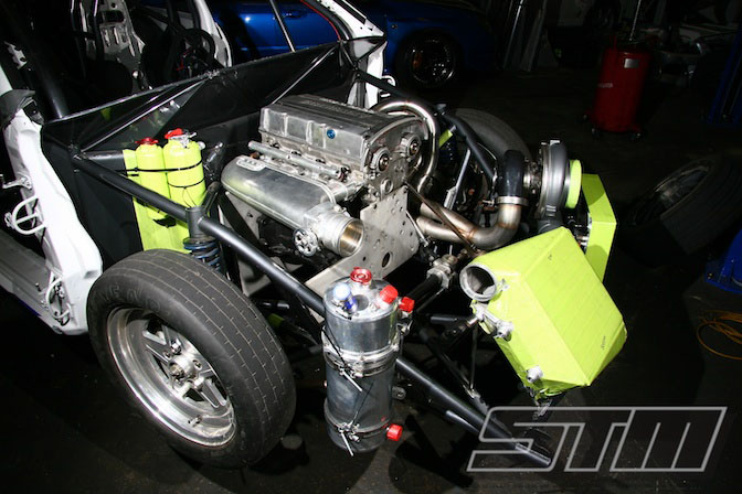
This is how the engine bay looked after rolling off the trailer at STM. The chassis was fitted with a dummy motor, and was yet to have the fuel system, dry sump or electronics fitted. That was the easy part though as after discussion with Mike, the decision was made to remake the exhaust manifold, intercooler and fuel/water tanks, significantly adding to the work required.
While the chassis was complete, there was a massive amount of work left before the car could turn a wheel at the track.
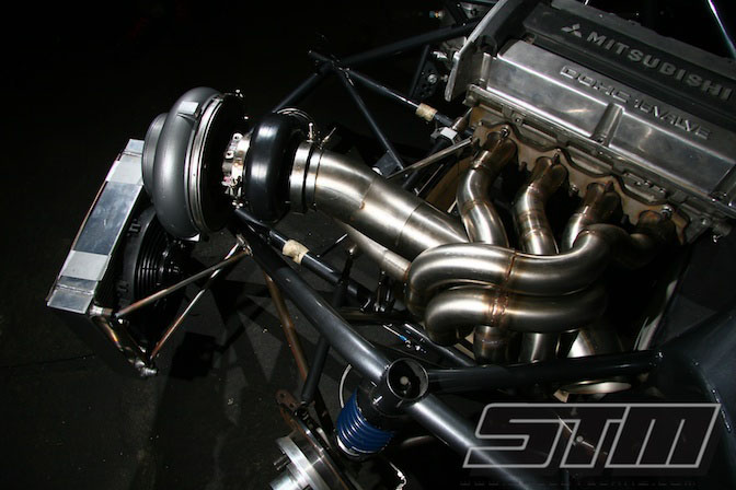
One of the first tasks was for Bam to get busy on the tig and fabricate a custom exhaust manifold to mount the Garrett GT45 turbo under the bonnet line. While there was a lot of work involved in doing this, Mike really wanted to keep the body lines clean.
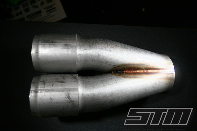
Bam started with a Burn’s Stainless 321 Merge collector. These collectors are a work of art and provide the ultimate flow into the turbo. This is critical to achieving good spool up without sacrificing top end power.
The manifold layout starts by positioning the turbo within the chassis and bracing it while the manifold is fabricated. The original Garrett exhaust housing has been swapped for a Tial Sport stainless v-band housing. These housings save about 8 kg and make removal of the turbo a snap thanks to the v-band flanges on the inlet and outlet.
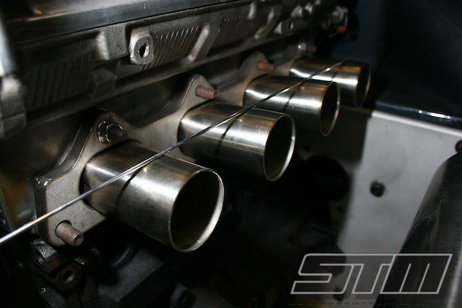
The manifold design required careful planning as despite the car being a tube frame chassis, room was still tight for the long-runner manifold. Here you can see the stainless header flange bolted to the dummy cylinder head as Bam begins fabricating the runners.
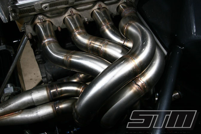
The manifold starts to take shape. Bam aimed for a long-primary header design which helps high rpm performance. The downside of this is that boost response can suffer due to the larger volume of the manifold. With a car like HD2, boost response isn’t too much of an issue though. With the 2 step launch control it is possible to have over 30 psi of boost on the start line if we want, and with the clutchless Liberty transmission there is no boost drop on gearshifts.
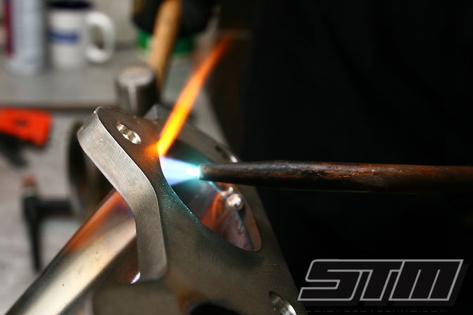
The 4G63 header flange uses an oval shape and here Bam heats the stainless runners so they can be manipulated into shape. The header tubes actually protrude through the header flange and are tig welded from the inside.
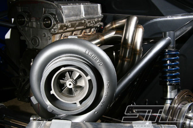
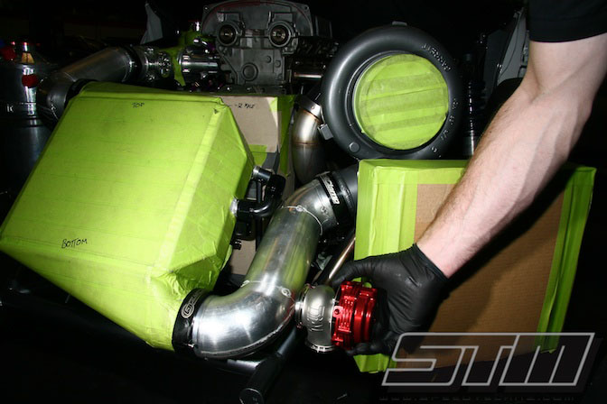
The huge Garrett GT45 sitting comfortably in its new home. With such a heavy turbo, properly bracing it to the chassis is essential. Bam whipped up a couple of adjustable rose-jointed supports to ensure that the manifold doesn’t crack under the mass of the turbo.
Would you like STM involved in your project? Contact us with your plans, budget and timeframe.
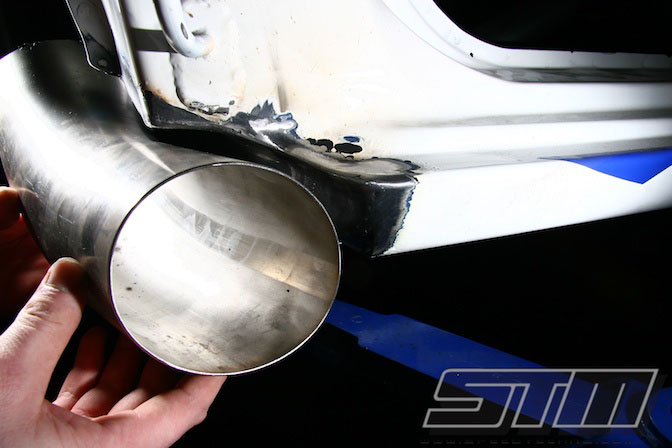
Once the manifold was complete Bam could get busy on the exhaust. With the driver being on the same side of the car as the exhaust, we wanted to make sure that no exhaust fumes entered the cabin. There is nothing pleasant about methanol vapour, and apart from being a health hazard it also makes your eyes water. We didn’t think Mike needed any more distractions at 180+ mph!
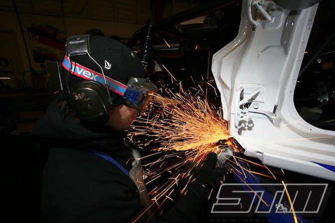
Bam decided to have the exhaust exit at the bottom of the sill but there wasn’t enough room to clear the front wheel at full lock. The solution was to cut a scallop into the sill so that everything fitted perfectly.
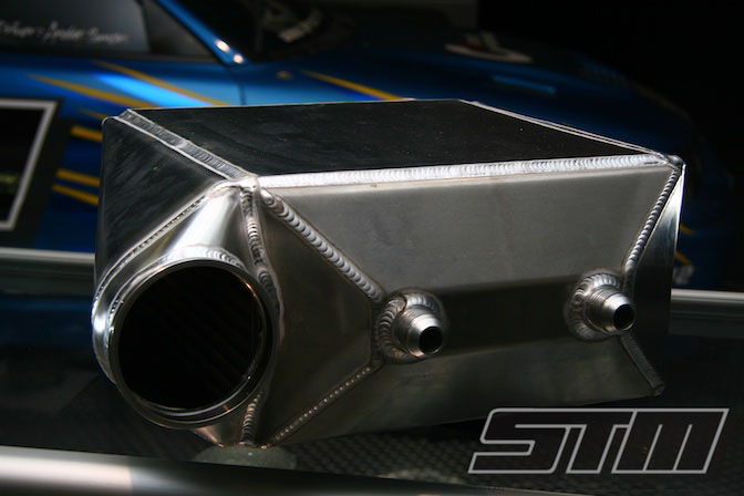
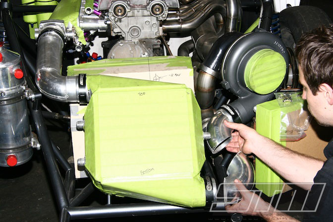
Once the manifold was complete, Bam turned his attention to the rest of the engine bay. Since the intercooler no longer fitted with the new turbo location, we took the chance to redesign it a little. This was the end result, fabricated by Jono from Motorsport Fabrications in Auckland. Jono is a true genius with a tig, and we have been using his skills since we built DOCILE.
The new intercooler is test-fitted in the engine bay. In this photo you can see the small radiator sitting below the turbo. While our methanol drag engines run solid filled blocks and only circulate coolant through the head, the car must be able to stay cool for the burnout, staging and the actual pass.
If an opponent finds out that your car has an overheating problem they could quite possibly play staging games on the line and ruin Mikes chances of getting down the strip. This isn’t going to be an issue for HD2 and the small purpose-built radiator will be enough to keep the engine temp under control.
In this photo the new intercooler is now fitted with some sturdy brackets being welded to the chassis. The intercooler core is quite heavy and Bam wanted to be sure that it didn’t move under the forces of a launch.
The new header tank and overflow can be seen on the firewall, and the large tank in front of the right wheel is the reservoir for the dry-sump system.
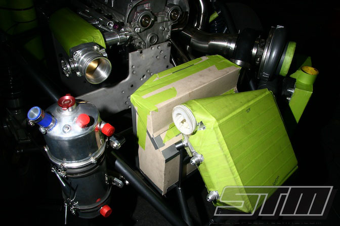
With all of the custom fabricated parts, the two plastic Jaz tanks for fuel and water just didn’t look right anymore. Bam designed a custom tank to fit in the space between the intercooler and the engine. The tank is a split design to take the methanol fuel on one side, and an ice/water slurry on the other side which is pumped through the intercooler core.
Once the design was finalised it was fabricated from alloy by Jono at Motorsport Fabrications.
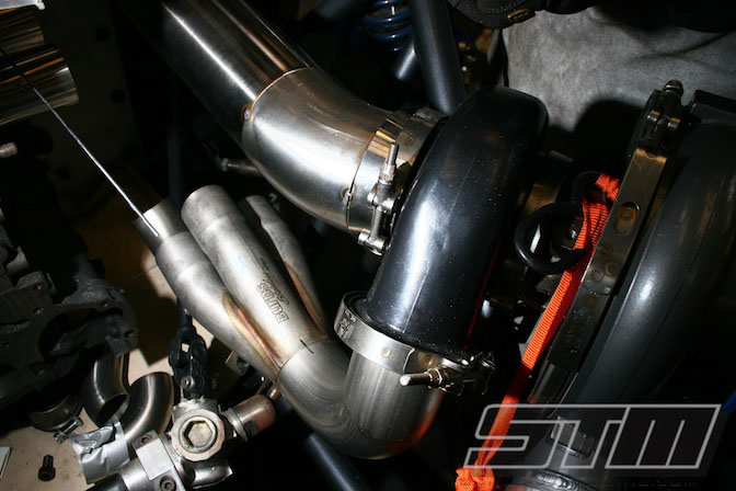
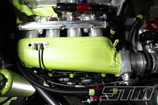
Fabrication of the intercooler plumbing is next. This was done in 90mm alloy tube to match the outlet of the turbo, and the 90mm throttle body on the Hyper Tune plenum. We are using ‘Gas Clamps’ from Gas Motorsport in Australia on the end of each pipe. These clamps seal with an o-ring and allow some flexibility without the chance of a hose popping off which can occur with silicone joiners.
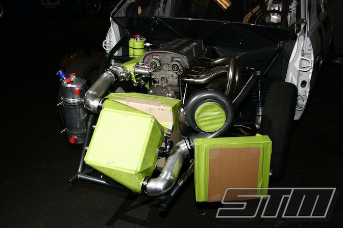
With the intercooler plumbing finished, HD2 is starting to look like a drag car!
To complete the intercooler plumbing Bam still needed to fit the Tial 50mm BOV, and the Tial 44mm wastegate. The BOV works in the conventional way and eliminates compressor surge when Mike lifts at the end of a pass. The wastegate is used during staging to ensure consistent boost every time, and instant response from the turbocharger when mike leaves the line.

The finished fuel/water tank is now installed and despite the complicated design, the fit is perfect. We have included a pair of Peterson Fluid System caps to allow easy filling between rounds.

Bam starts making up the lines to connect the intercooler to the tank. The tank has an internal water pump to make the installation and connection easier.
The engine for HD2 is a custom 2.1 litre long-rod design which gives a slight increase in capacity without sacrificing the engine’s ability to rev. We are using a custom JE forged piston which will give a compression ratio of 11.0:1. While this is quite high, with the methanol fuel allows us to run very high compression ratios even with 50-60 psi boost pressure.
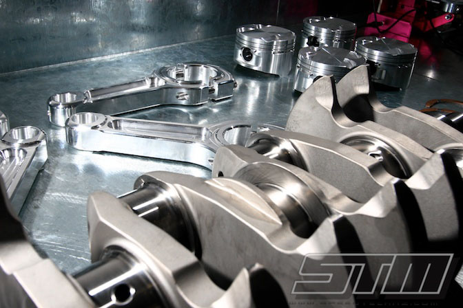
The billet crank uses a 92 mm stroke which is just a little shorter than the more common 2.2 Litre 94 mm crankshafts. The 92 mm stroke allows us to use a projected 10,500-11,000 rpm redline while retaining a maximum piston speed that is still acceptable.
The beefy alloy rods were selected to reduce reciprocating mass which is an advantage at the sort of rpm we expect to run. Alloy rods are naturally a little softer than a steel rod which means they don’t transmit so much shock loading back into the big end bearings and crankshaft. The downside of alloy rods is that they have a fatigue life and typically they need to be replaced after around 50 passes.
HD2’s engine starts out as a regular EVO 8 block, but there is a lot of work required to get it to handle 1200+ hp. We start by filling the water jackets in the block with a cement-based block filling compound. This compound has the same thermal expansion coefficient as cast iron and greatly improves the integrity of the engine block as flexing of the cylinder walls is greatly reduced under high boost.
A solid filled block is a drag-only modification as there is no longer any water flow through the block. This only works because of the cooling properties of the methanol fuel and the short run time that the engine will experience. We still run water through the cylinder head as this is where the majority of the heat builds up.
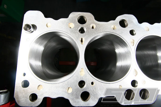
Once the block is solid filled, it is torque-plate honed to suit the new JE forged pistons. Torque plate honing replicates the distortion the block will see when the cylinder head is bolted down, and this ensures that the bores are perfectly round when the engine is running. Torque-plate honing improves ring seal which increases power and reduces blow-by.
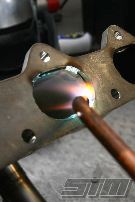
In this photo you can also see the o-ring grooves machined into the deck face of the block. We use a special stainless o-ring which bites into the head gasket and helps keep the head sealed at very high boost levels.
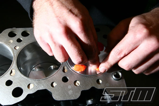
In this photo the engine is being dummy assembled to check valve-to-piston clearance. We are using a very aggressive cam profile in this engine to allow it to breath well at 10-11,000 rpm and this involves a high valve lift. The engine is assembled with play-doh in the valve pockets and then the crank shaft is rotated a full 720 degrees. After disassembly we can very accurately check the valve clearance by inspecting how much the play-doh has crushed.
With an alloy rod we need to allow some additional clearance over what we would expect with a steel rod since the alloy will actually stretch slightly at very high rpm.
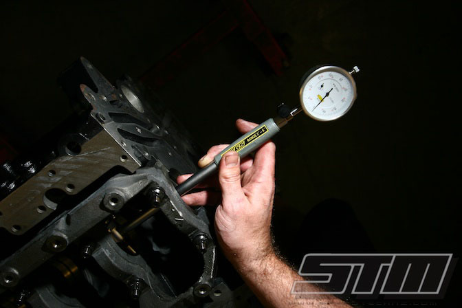
Confirming bearing clearances is critical with any engine, but when you are expecting 1400+ hp the importance steps up a notch. Here a bore gauge is being used to check the size of the main bearing journals in the engine block. We check each journal to ensure it is on size and has no taper or ovality. If any measurements are outside of specification then the main tunnel will require line honing to ensure it is perfect.

Measuring the crankshaft journals is just as important as measuring the journals in the engine block. Again we are looking for a uniform size with no taper or ovality. Each journal is measured in 3 positions across its width and also in two planes. With the measurement of the crank journal and the bearing tunnel we can also confirm our bearing oil clearances. If the clearances are not exactly right then corrective machining is required.
These are the basics of engine building which must be 100% perfect if we want a powerful and reliable engine. Unfortunately these techniques are too often overlooked.
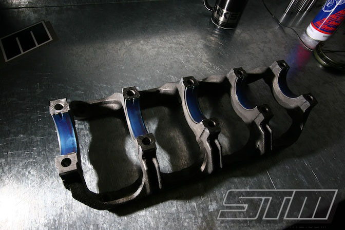
Once all the clearances have been confirmed, the engine is ready for a final assembly. Here the main cradle is cleaned and fitted with the new ACL race series main bearings. Prior to installation the bearings are coated with a special lubricant which will protect them while we gain oil pressure prior to the engine’s first start up.
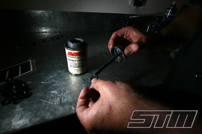
To make sure that we achieve accurate and consistent torque settings on all the engine fasteners, ARP moly lube is used. Commonly a light weight engine oil is used, but the ARP lube does a better job of reducing friction which ensures that all the fasteners are tightened correctly.
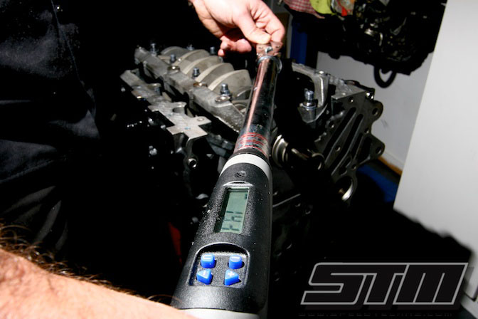
Achieving the correct torque is critical in a highly stressed engine and with 1400+ hp and 11,000 rpm, the stress and loading on all of the components are immense. Here the main cradle is being torqued up during final assembly. We use a high quality Snap-on digital torque wrench to achieve very precise torque and ensure the best results.
While most fasteners are tightened to a specific torque setting, the preferable way is to tighten the fastener to achieve the correct amount of stretch. A bolt or stud acts like a tiny coil spring, and stretching the fastener is what provides the clamping force that holds two parts together.
In a ‘blind’ installation such as a head stud or a main stud, it isn’t possible to measure stretch but with a conrod bolt we can usually get access to both sides of the fastener. Here we are using a stretch gauge to achieve the recommended stretch in the 3/8” L19 rod bolts.
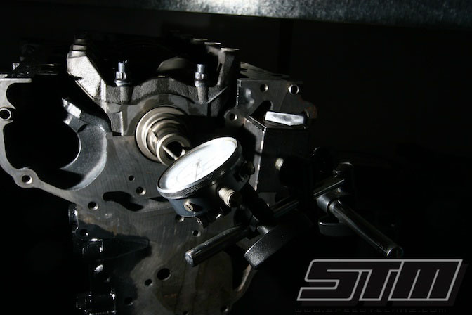
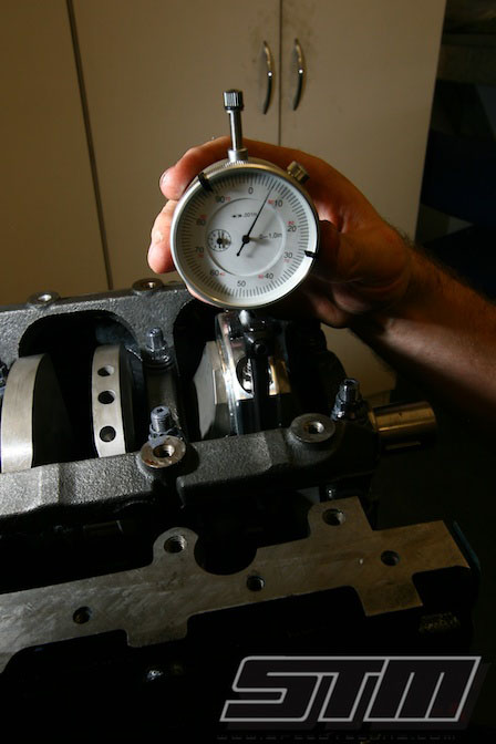
Here a dial gauge is located onto the snout of the crankshaft to confirm that the crank end float is within specification. Thrust bearing failures were common on the earlier EVO 1-4 engines, resulting in a phenomenon called ‘crank walk’. The late model blocks use separate thrust washers and do not suffer from these same failures but we still need to check the end float.
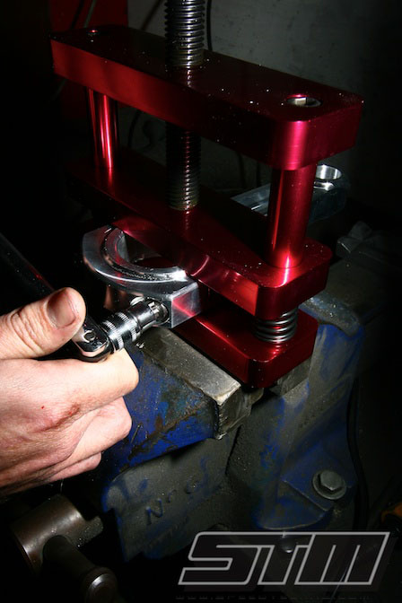
Aluminium rods are great for reducing reciprocating weight but they require a little more care during assembly. Any scratches or marks left on the rod can cause a stress raiser which may result in the conrod cracking or failing prematurely.
Here we are using a special conrod vise which clamps the rod while the rod bolts are being worked on. This ensures that the conrod doesn’t get scratched while it is being handled.
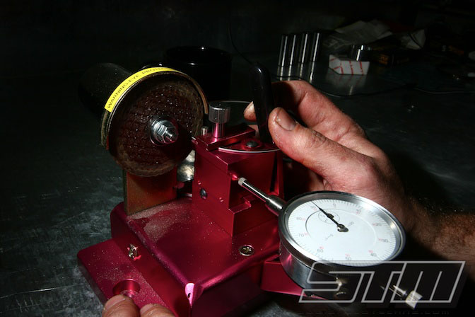
Most aftermarket pistons are supplied with a ‘file-fit’ ring set. This means that the rings are too large and the ends need to be filed to achieve the correct end gap. Once the engine is up to running temperature the rings will expand, and we want a ring gap that is as tight as possible. A tight ring gap reduces blow-by into the crankcase and reduces oil consumption. There is also the potential for a little more power.
Here an electric ring file is being used to gap the piston rings. This file includes a dial gauge which makes it easy to achieve accurate and consistent ring end gaps.
A production head casting can suffer from discrepancies during the casting process so after the port work has been completed we check each combustion chamber to ensure it is a uniform volume. This ensures that the compression ratio will be consistent across all four cylinders.
A really important step in porting any cylinder head is to ensure that any sharp edges or casting dags are removed and smoothed. If left untouched they can promote detonation and really limit what we can achieve with the engine.
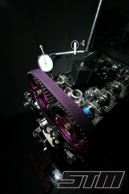
Adjusting the dial-in of the camshafts has a big impact on the power an engine will produce, as well as the torque curve of the engine. With a drag engine we are only really interested in the power band between 8000-11,000 rpm and the camshafts are dialled in to optimise this area of the rev range.
Usually we will start with a known baseline for the particular camshaft grind and then optimise it on the dyno as required.
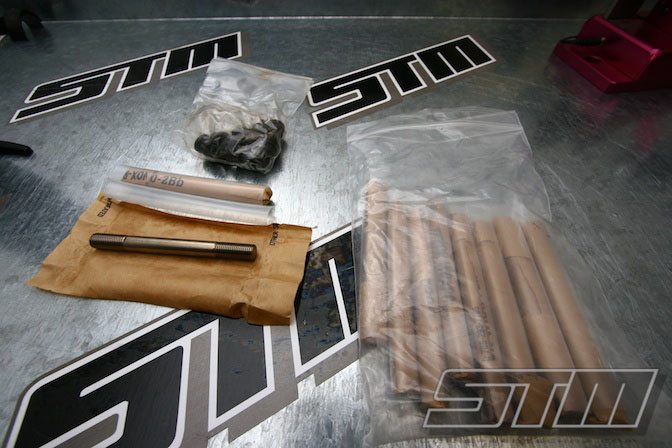
With a build like this, often expensive engine parts come in depressingly anonymous plastic bags. In a high-end drag engine, sealing the cylinder head to the engine block is one of the most difficult aspects. With very high boost levels (50-60+ psi), the combustion pressure is so great that the head literally lifts off the block, resulting in head gasket failure.
These ARP L19 head studs are made out of a material with a much higher tensile strength than a stock head stud which means that we can achieve a greater clamping force.
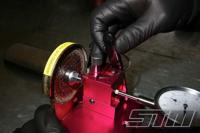
JE pistons are supplied with file-fit ring sets so that the end gap of the rings can be set by the engine builder during assembly. The desired end gap will depend on the heat that the ring can be expected to see and this will depend on the boost level, power, rpm, fuel and application. A ring gap that is too wide will result in excessive blow-by, oil consumption and less power, while a ring gap that is too tight can cause a catastrophic engine failure.
Here Ray is using a special electric ring file which is fitted with a dial gauge. This allows the ring gap to be set very accurately, and the ring gap can be kept perfectly parallel.
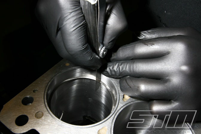
In this photo Ray is checking the ring end gap after the ring has been filed. It is important to make sure the ring is located 20-30mm down the bore to get an accurate reading. Each ring is gapped individually for each bore and they are kept in order prior to fitting them onto the pistons.
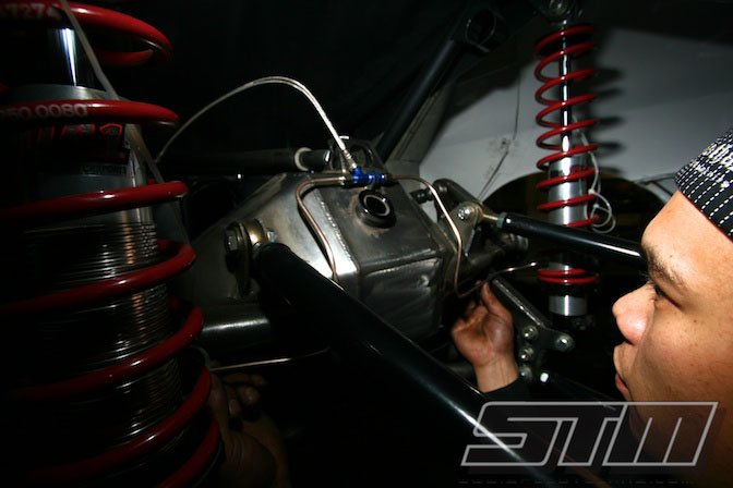
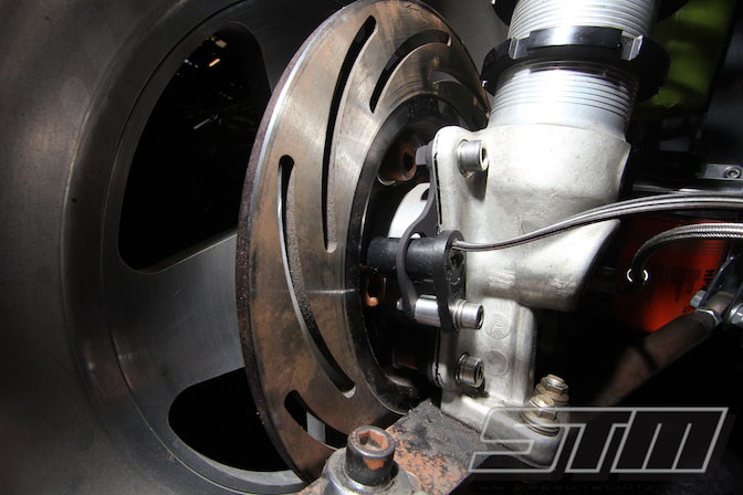
Ray makes up brake lines to suit the 4 pot Mark Williams brake callipers. In this photo the size and strength of the diff housing is obvious. The diff housing is a fabricated 9” unit from Jerry Bickel Race Cars, and was finished by Top Gear Autotech.
The diff is fitted with a Mark Williams alloy diff head which is equipped with 9” Pro Gears designed specifically for drag racing. The Pro Gears have a softer surface hardening than a regular crown wheel and pinion. The softer gear is less likely to crack, however they would also wear quickly in extended use – Lucky this diff is only ever going to travel 400 metres at a time!
Other drag-only modifications include a support bearing for the end of the pinion. This stops the pinion from flexing away from the crownwheel which can cause failures in very high power applications.
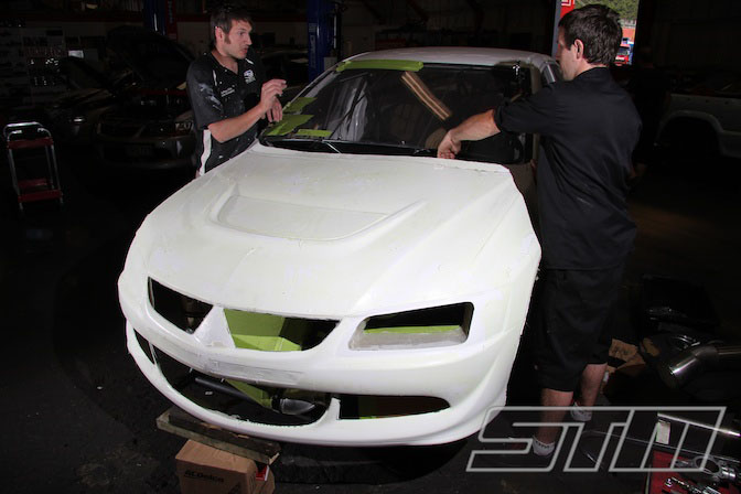
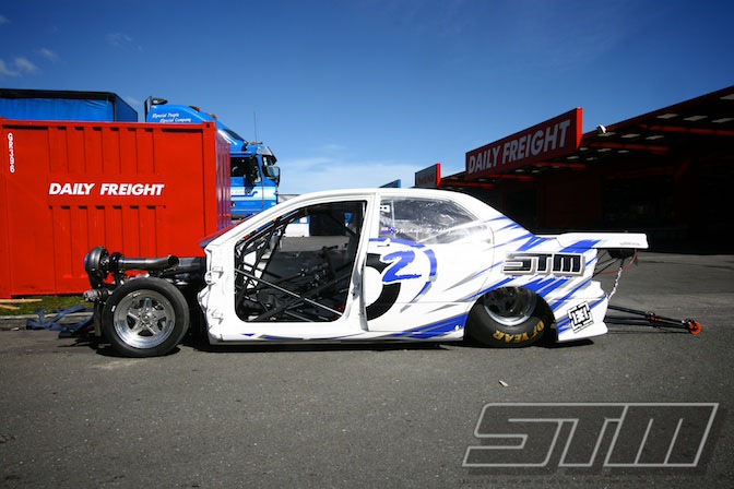
Zac from Carboglass is a magician when it comes to anything made from fibreglass or carbon. We weren’t happy with the shape or fit of the original front body and Zac took on the job of sorting it out. The new nose has been stretched slightly and reshaped to provide a better fit around the base of the screen and improved aerodynamics.
Here Bam is confirming the fitment before Zac finishes it off. In the final form the holes in the front bumper will be closed up with the exception of the intake for the turbo.
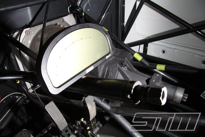
On the inside Bam made a mount for the Motec SDL dash unit. The SDL dash is an advanced display and datalogger which is invaluable for analysing run data in a drag car. While Mike won’t get the chance to look at it during a run, it communicates to the Motec Shift light Module (SLM) to tell Mike when to change gears, and will display a warning light if there are any problems.
The SLM and warning light are enough to get Mike’s attention without him needing to look specifically at the dash during the run. If a warning is triggered, Mike can glance at the dash which will display the actual warning message.
A wheel speed sensor is fitted to the front right wheel so that we can datalog ground speed. If we use a rear wheel for a speed input then the data is inaccurate when the car wheel spins. A 34” slick will also grow in diameter by over 2” at 180+ mph, so the actual ground speed is more accurate if we use a front wheel sensor.
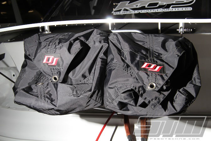
We expect HD2 to be able to trap at speeds of 180+ mph once we start leaning on the tune later in the season. At these sort of speeds we only legally need one parachute, however our own experience at tracks with a short shut-down area like Meremere means that we would prefer the safety of a second chute to make sure stopping is never a problem!
Coupled with the twin chutes is the normal braking system in the car. This includes twin piston Strange callipers on the front and the 4 piston Mark Williams callipers on the rear. All of this is operated by a Tilton pedal box with an adjustable brake bias.
Bam designed a custom header tank and over flow for the cooling system and had these fabricated by Motorsport Fabrications. The finished product is stunning.
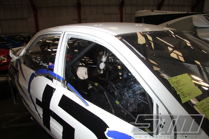
Light weight doors don’t have the rigidity to stay properly closed at high speeds. Since we don’t want anything distracting Mike from his job of driving, JBRC door catches have been fitted to the front doors . These clip onto a bracket on the cage after the door is closed and prevent the door from opening at high speed.
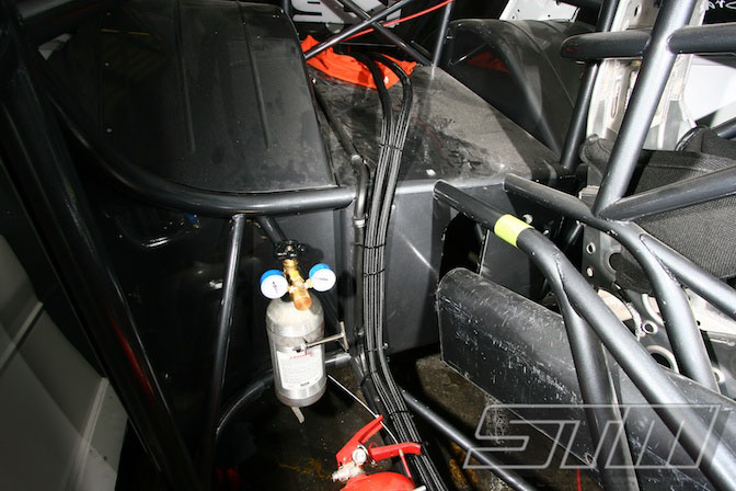
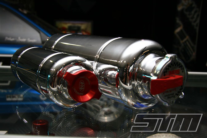
NZDRA rules require a large catch tank which is plumbed to collect any blow-by from the engine to ensure nothing gets on the track. Bam fabricated a 4 litre tank which he fitted into the rear of the car and plumbed with -12 lines.
The tank is fitted to the rear of the car so that if for any reason there is a problem with the engine and the tank over flows, the excess will be dumped behind the rear slicks. This eliminates the chance of oil or water getting under the slicks and causing Mike to lose control. A simple ball-valve is included to allow the tank to be drained quickly and easily between rounds.
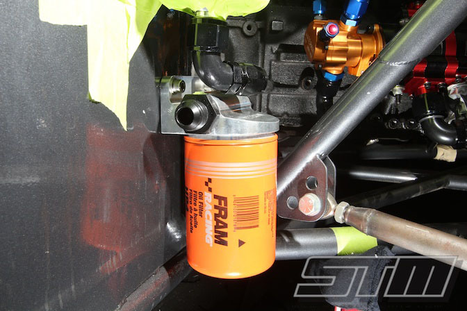
A Peterson remote oil filter mount is fitted to the firewall. This allows us to use a large Fram racing-type oil filter which has a much larger filtration area. With the remote mount, it is quick and easy to remove the filter for inspections if necessary.
In the background you can see the Peterson 4 stage dry sump pump which is driven directly from the crankshaft. This pump includes 3 scavenge stages which draws oil directly from the custom sump. A dry sump system reduces windage losses from oil vapour in the crankcase which provides a little more power while offering more reliable lubrication.
On the back of the dry sump pump is a Waterman mechanical fuel pump. This is responsible for supplying fuel to the engine, and despite its size, it is capable of supplying enough methanol for well over 2000 hp!

Here we can see some two of the in-line fuel filters. The fuel system plumbing is quite complicated as we are using twin fuel rails with a total of 8 ID2000 injectors. Mechanical fuel pumps are not very good at providing good pressure at cranking speeds, so we have also incorporated an electric primer pump to pressurise the system initially and ensure easy starting.
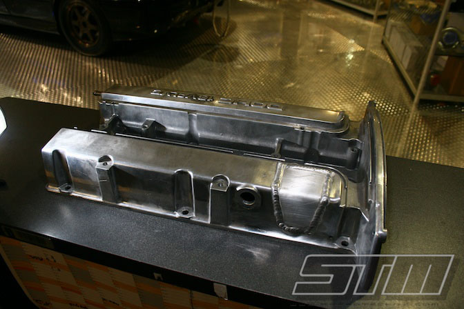
Since we are using a dry sump system, there is no longer any need for an oil filler cap – The oil level is checked and topped up through the top of the dry sump tank. We decided to remove the section out of the factory rocker cover and smooth it off. This means there is no chance of the oil filler cap falling off, and it improves the aesthetics. The cover will be powder coated prior to installation.
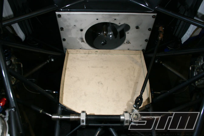
Any drag car running quicker than 8.99 must have a ‘lower engine containment device’ or what is more commonly referred to as a ‘nappy’. This means if the engine throws a rod or otherwise suffers some catastrophic failure, no oil ends up on the track.
Due to the pumps etc that are mounted off the engine, we chose to build a tray instead of a nappy. This tray will be filled with an absorbent material which will soak up any oil should the unthinkable happen. Here Bam is making a card template before the final tray is moulded in carbon fibre.
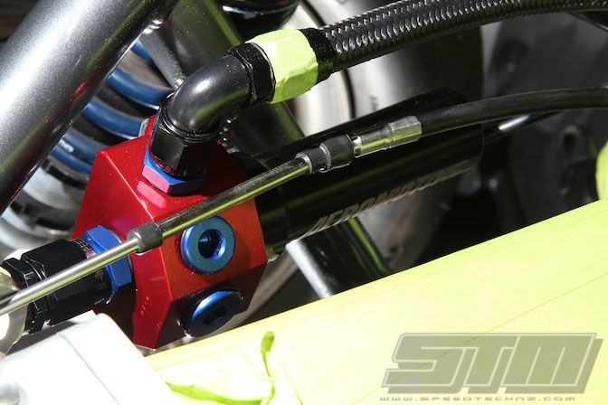
The Aeromotive fuel pressure regulator is mounted. These regulators are designed specifically for mechanical pumps, and have a very high valve lift to ensure consistent fuel pressure across a wide range of rpm.
The Morse cable for the throttle is also visible in this picture. Instead of a normal cable for the throttle, we are using a solid Morse cable. This is a solid push-pull cable which means that if the throttle jams Mike can actually pull it closed with the loop on the top of the throttle pedal. This is an NZDRA safety requirement.
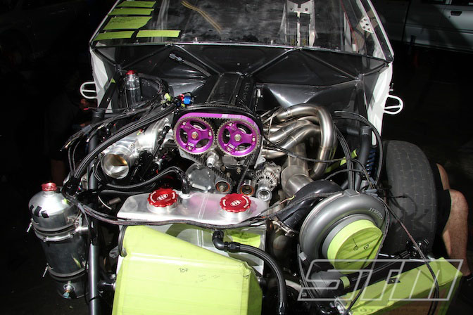
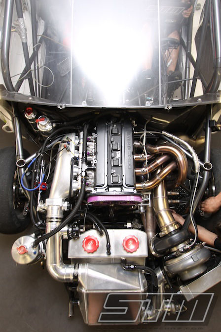
The engine bay starts to take shape. At this stage most of the fabrication is finished and it is now a matter of running all of the lines and hoses. The car is still fitted with a dummy engine at this stage, and we still haven’t started on the wiring for the Motec electronics.
We finally had the chance to get the car onto our dyno but quickly found out that the engine was a little too much for our dyno to handle. With the very short 5.1 final drive, the torque at the axles was too much for our Dynapack Hub dyno, shutting it down at only 7500 rpm. At this point the engine was producing around 900 whp and 700 lbft of torque. Considering both the torque and power were both going vertical and we would expect this engine combination to make peak power at around 9500-10,000 rpm, you do the math!
We will get the car back on the dyno in the near future with a taller diff ratio which will let us run the engine well past 1000 whp. Our problems were made worse by the wastegate spring which was providing 40 psi boost pressure as our minimum level! This may be a bit much for some of NZ’s tracks, so a softer spring will go in before the next dyno session.
Built by STM (Speedtech Motorsport, New Zealand)
http://www.speedtechnz.com
Photos by Ben Silcock
Words by Andre Simon

Sponsors
Horizontal Drilling Division – http://www.horizontaldrilling.co.nz/
Sparktech Ignitions – http://www.sparktechignitions.net/
Motul NZ – http://www.motul.co.nz
Very Special Thanks
Bam Blaikie, Doug Goodall, Ben Silcock, Andre Simon, Ray Yee, Chris Wall @ STM (Speedtech Motorsport Ltd)
Phil Smalls @ Redline Performance
Craig @ Sparktech Ignitions
Jono @ Motorsport Fabrications
Zac @ Carboglass
Karl @ Cemac Engineering
Nyle & Clinton @ GSS Performance
OFFICIAL SPEEDHUNTERS SUPPLIERS


Dam thats HOT!
wheres the evo bit?
fuck me, that's amazing
awesome write up, and amazing work.
Simply amazing. last photo for desktop!! : >
Looking good! Enjoying all the fabrication in these frequent postings.
bam, whoever you are, keep doing your thing.
plenty of info here.. that turbo is huge!! some top quality engineering going on - excellent blog.. top notch photos..
Sick build, keep up the great work !
Looking forward to seeing this run. Another beast from STM!
...
...
...
...
...
...
...
...
So it's not a real EVO any more.
Now this build is interesting. Thanks im so sick of ae86 projects.
This is a SERIOUS professional build here. top notch work across the board, no shortcuts, no fooling around.
You guys are the real deal. Mad props to you all.
holy sweet jesus, that is pure automotive porn. fantastic stuff
My mind is blown. Great pics and write up!
I'm loving the fact you are showcasing the shops and builds from Aus and NZ. They do amazing stuff and have been for years. Probably my favourite posts you guys do as of late.
compare the turbo n the motor = wow what a big ass turbo !!!
people still drag race?
that shits gonna fly
This was a good read! I learned a bit of stuff, especially regarding the build of the engine.
Wow, best write-up I've seen on this website. Finally, technical detail written by someone intelligent... Hallelujah!
oh, very professional and well-thought out drag car too!
hi please anyone knows i have 18 inch rims on my car and i want to buy new tiers if i made the rear tiers with big profile like 50 and front 40 would it made my handling better or worse ??
now i have 235 40 18 for all the tiers
pls reply me on my email mallah656@hotmail.com
many thanks
New Zealand and kiwi's representing - very very chur!
Monumental build!
Amazing writeup. I love all the detailed technical information. More more more!
holy jebus look at those beads on the air to water I/C.....like a machine did it...........huge props
Def the best build thread of the entire month.
So much Detail, So much Tech, So Much Goodness...
Not my Cup of tea for an Evo, But Madd Respect to them and to the detail and genius thats been put in this build.
I am finally happy with Build Month...
holly crap!!! that turbo's massive!
Maybe im behind the curve but is it common to put the wastegate on the charge pipe and not the exhaust manifold? I can see how it would work, but i know on my car my wastegate in on the manifold.
So very impressive....
Wow. Impressive and inspiring. Let see some dyno sheets and maybe a vid or two of a couple passes if you please =)
Very elaborate read, enjoyed every bit of it! Now I gotta change the page before work calls this porn!
Hi there guys,
Thanks you for your comments. The team here at STM is really stoked you enjoyed the build thread. You can check out our You Tube account for videos.
http://www.youtube.com/user/SpeedtechMotorsport
For photos and news on the HD2 Drag EVO join our Facebook page.
http://www.facebook.com/STM101
Andre will jump online later today and answer your tech questions.
Wau I love it
starion?
I'm admiring the actuality you are showcasing the shops and builds from Aus and NZ. They do amazing being and accept been for years. Probably my favourite posts you guys do as of late. The photos are impressive. The acquaint photos are actual adorable to skip the visitor. And all the pics affair is actual likeable. I adulation your column photo. Well job!!!!:)
Well, if you're answering questions, I was wondering what the reasoning behind wastegating the compressor instead of the turbine was? and what sort of variance do you see between your EGTs cylinder-to-cylinder during a run?
@ Ahmad
WTF? What are you on buddy?
@ Ben
We still use a regular exhaust manifold wastegate for boost control during a run. The wastegate on the intercooler is only used to control boost during staging/launch. this gives stable boost and faster turbo response.
@ m
See above. We aim to have EGT's matched within 10-15 deg C across all cylinders
What a great post!! As an engineer I really appreciate all the work you guys put into building a motor to this level. It was nice to read how professionally indepth you went into the build ! Can't say it enough Great POST !!
hay Andre just wondering what kind of ball park figure i would be working with to get this treatment on my RB as i have been thinking about contacting Robby ward in rotorua about building my engine but after reading this build thread i would like to see if you can work with an RB as opposed to a 4G
@Andre: Thanks for the answer! I am more of an open track guy than drag racing, but i like the idea of boost control by bleeding off pressure in the charge pipe and not letting exhaust gas bypass the turbine wheel. Is there a reason you only use that wastegate to control boost at launch and not the whole pass?
@ R32GTR
We would be happy to work with you on an RB project. Your options are limitless and cost will vary accordingly. Please email info@speedtechnz.com with your requirements.
@ Ben
The downside with controlling boost entirely on the charge side is that you will overspeed the turbo. This usually results in the turbo moving out of its efficiency and hence the charge air becomes super heated. Back pressure in the exhaust manifold is also increased which affects the dynamic airflow through the engine.
While it can be done, my advice is to stick to a conventional exhaust manifold wastegate for boost control
This reminds me of a vehicle I was playing with when I was sixteen or so. I was building a 93 Mirage with this same basic rear wheel drive setup and although I got it togeather with a 4G63, a TSI rear-end, a Starion bellhousing and driveshaft, and a MK4 Supra gearbox (no joke)... I never got it running and ended up selling it. I'm expecting to end up seeing it on here some time sooner or later.
@ Andre
Thanks for another response, i didnt really think about it pushing the turbo out of its efficiency range. Keep up the great work!
pro drag car is really not my thingy...but n evo with its 4g pointed north-south? GONNA LUV IT!!! XD
P.S. why the kiwi projects always appeals 2 me???
Channel type Cable Organizer manufactured out of Rigid PVC with punched side slots for cable entry/ exit fixed on Steel sheet punched Back panel and Loop Type will have ABS Loops fixed on steel sheetp punched back Panel with highest quality standards under stringent ISO 9001-2008 Manufacturing & Quality management system to ensure highest quality product.
That is some Great DSM work GOOD JOB!!
Until
alternatives are massively available, efficiencies are improved, and polluting
byproducts are diminished to a sustainable level, we need to use all the
resources we have available to us. That includes conservation and using less
energy. But here, we are fighting an inertia.
schultzy @ https://www.yourmechanic.com/
Why not a Dynojet they are able to read 1400hp per drum .?